2-6
2000-DSS COMBINED SONAR
0009335_REV_D
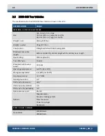
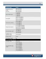
SPECIFICATION
VALUE
Vertical resolution
:
19 cm (1–5.0 kHz)
12 cm (1.5–7.5 kHz)
8 cm (2–12 kHz)
Penetration in coarse and
calcareous sand
:
30 m (typ)
Penetration in soft clay
250 m
Beam width
:
41°, 0.5–5 kHz
32°, 1–6 kHz
24°, 1.5–7.5 kHz
16°, 2–12 kHz
Optimum tow vehicle
pitch/roll:
<16°, 0.5–5 kHz
<13°, 1–6 kHz
<10°, 2–8 kHz
<8°, 2–10 kHz
<7°, 2–12 kHz
Optimum tow height:
3–5 m above sea floor
Transmitters:
1
Receive arrays:
4
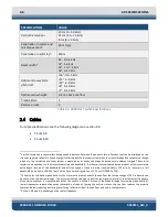
Table 2-3: 2000-DSS Towfish Specifications
2.4
Cables
For cable specifications, see the following diagrams in section
•
•
4
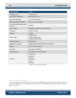
Vertical resolution is the smallest distinguishable distance between the peaks of two reflections that can be displayed on the
screen as separate reflectors. Sound energy is reflected back to the sonar system when the transmitted pulse encounters a change
in density. The resolution of a sonar system is measured by its ability to distinguish between two adjacent targets. The vertical
resolution is dependent on the transmitted chirp pulse bandwidth. It is theoretically calculated by the product of the transmitted
pulse length (inverse of the bandwidth) and half the speed of sound in water (approximately 750 m/s). For example, a full
bandwidth pulse from an SB-424 Tow Vehicle has a vertical resolution of 3.75 cm (1/20,000 x 750).
5
The value for sub-bottom penetration is the maximum distance beneath the sea floor that a step change of 10% in density can
be seen on the sub-bottom display. This assumes that the sediment is gas free (no organic materials), that the lowest frequency
of the pulse spectrum is transmitted and that the vehicle is within 5 meters of the seabed (range for maximum penetration).
Lower frequencies reduce attenuation (absorption of sound). Towing the vehicle close to the sea floor reduces the acoustic
footprint thereby reducing scattering (interfering reflections) from the sea floor and within the sediments.
6
At the -3 dB points, depending on the center frequency.
Summary of Contents for 2000-DSS
Page 20: ......
Page 56: ...Figure 4 2 2000 Digital Telemetry Link Electronics Block Diagram...
Page 57: ...Figure 4 3 2000 Digital Telemetry Link Wiring Diagram...
Page 59: ...Figure 4 4 Tow Vehicle Electronic Block Diagram...
Page 60: ...Figure 4 5 Tow Vehicle Interconnect Drawing...
Page 63: ...Figure 4 6 Armored Cable PMI Grip Unterminated Topside...
Page 64: ...Figure 4 7 Test Cable...
Page 77: ...5 13 Figure 5 16 Magnetic Declination Estimated Value Screen...
Page 79: ...5 15 getDeclination CR Figure 5 18...
Page 80: ......
Page 94: ......
Page 96: ......
Page 98: ......


