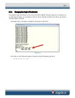


6-9
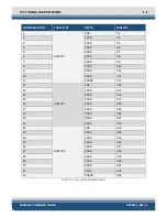
+12 VDC +/-0.6V
-12 VDC +/-0.6V
Test Lights:
1.
Power Distribution Board.
Monitor the +400 volt D4 and +48 volt D8 LED's. They should be on steady.
2.
SSB Board.
There are two LED's of interest. 'LED A' flashes when 120 kHz is transmitting. 'LED B' flashes when
410 kHz is transmitting.
3.
SIB Board.
There are four LED's of interest. They have the following status when the system is operating
properly.
D1 Off
D3 (Orange)
Flashes at 2 Hz
D2 Off
D4
(Green) On
6.3.7.4
SSB Board Test Points
1.
GAIN A and B test points show the positive-going TVG ramp voltage for the low and high frequency
sonar channels.
2.
Four test points monitor the TVG’d analog sonar data. They are:
ADC 0 Port
SSL
ADC2 Stbd SSL
ADC 1 Port
SSH
ADC3 Stbd SSL
These test points are useful when doing a rub test.
6.3.7.5
DDC Test Points
This board does not have any test points. LEDs monitors display the channels on the card that are running.
Side A and Side B. In a normally operating vehicle with both channels collecting data the lights will
alternate.
6.3.7.6
Modem Board Test Points
1.
FSK.
Monitors the 3200 kHz to 2800 kHz frequency-shift-keyed signal from the topside unit. This signal
is used for optional commands. May not be present in all systems.
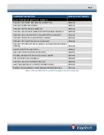
Summary of Contents for 2000-DSS
Page 20: ......
Page 56: ...Figure 4 2 2000 Digital Telemetry Link Electronics Block Diagram...
Page 57: ...Figure 4 3 2000 Digital Telemetry Link Wiring Diagram...
Page 59: ...Figure 4 4 Tow Vehicle Electronic Block Diagram...
Page 60: ...Figure 4 5 Tow Vehicle Interconnect Drawing...
Page 63: ...Figure 4 6 Armored Cable PMI Grip Unterminated Topside...
Page 64: ...Figure 4 7 Test Cable...
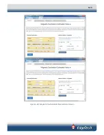
Page 77: ...5 13 Figure 5 16 Magnetic Declination Estimated Value Screen...
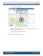
Page 79: ...5 15 getDeclination CR Figure 5 18...
Page 80: ......
Page 94: ......
Page 96: ......
Page 98: ......


