4-24
2000-DSS Combined Sonar
0009335_REV_D
4.2
Tow Vehicle
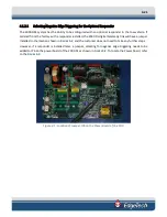
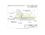
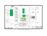
A photo of the 2000-DSS Tow Vehicle electronics chassis is shown
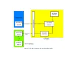
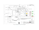
, and a block diagram and
, respectively. The electronics chassis contains all of
the tow vehicle circuit boards along with the optional pressure sensor. The circuit boards are the
following:
POWER DISTRIBUTION
The Power Distribution board inputs the tow vehicle 400 VDC
power on J1 from the 2000 Topside Processor over the coaxial
tow cable and filters it from the frequency shift keyed (FSK)
responder trigger signals and the ADSL downlink command and
uplink data signals. The command signals are input and the data
signals are output on J2. The Power Distribution board also
includes DC to DC converters which convert the 400 VDC to +48,
+12, 12, and -5 VDC. The +48 VDC is output on J4 to the Amplifier
boards. The other voltages are output on J6 to the ADSL Modem
board, J5 to the CPU board, J7 to the Sonar Interface board, J8 to
the Option connector, and J9 and J11 to the fans.
ADSL MODEM
The ADSL Modem board converts the downlink command ADSL
signals received from the 2000 Topside Processor and input on J2
from the Power Distribution board into Ethernet
10/100/1000BaseT signals which are output on J1 to the CPU
board. Similarly, the ADSL Modem board converts the uplink
Ethernet 10/100/1000BaseT based data signals from the CPU
board into the ADSL uplink data signals which are output on J2 to
the Power Distribution board for transmission to the 2000
Topside Processor. The ADSL Modem board also outputs the FSK
responder trigger signals on J5 to the Sonar Interface board and
to the optional Responder board. +12 and -12 VDC power is input
on J8 from the Power Distribution board.
T/R SWITCH
The T/R Switch board provides the transmit/receive function for
the side scan transducer arrays, allowing them to be used both
as acoustic transmitters and as acoustic receivers
simultaneously. Transmit signals are input from the Power
Amplifier board as follows:
•
J1:
Port low frequency transmit
•
J2:
Port high frequency transmit
•
J3:
Starboard high frequency transmit
•
J4:
Starboard low frequency transmit
Summary of Contents for 2000-DSS
Page 20: ......
Page 56: ...Figure 4 2 2000 Digital Telemetry Link Electronics Block Diagram...
Page 57: ...Figure 4 3 2000 Digital Telemetry Link Wiring Diagram...
Page 59: ...Figure 4 4 Tow Vehicle Electronic Block Diagram...
Page 60: ...Figure 4 5 Tow Vehicle Interconnect Drawing...
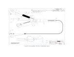
Page 63: ...Figure 4 6 Armored Cable PMI Grip Unterminated Topside...
Page 64: ...Figure 4 7 Test Cable...
Page 77: ...5 13 Figure 5 16 Magnetic Declination Estimated Value Screen...
Page 79: ...5 15 getDeclination CR Figure 5 18...
Page 80: ......
Page 94: ......
Page 96: ......
Page 98: ......

