3-1
3.0
SETUP AND ACTIVATION
Setup and test of the EdgeTech 2000-DSS Combined Side Scan Sonar and Sub-Bottom Profiling System
encompasses unpacking, inspecting and connecting the system components, including an optional
printer; connecting a navigation system and external sonar systems if required; activating the system; and
verifying operation using the EdgeTech DISCOVER software. This section provides instructions on how to
perform these tasks and how to deploy, tow and recover the tow vehicle.
3.1
Unpacking and Inspection
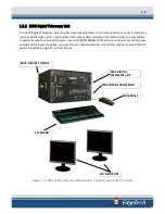
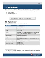
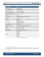
The 2000 Topside Processor, along with one LCD monitor, the keyboard, the trackball, software, and
system documentation are shipped in a reusable heavy duty transport case. The tow vehicle, the second
LCD monitor, a test cable, and tow vehicle accessories are shipped in a wooden shipping crate. Before
unpacking the system components, inspect the shipping containers for any damage. Report any damage
to the carrier and to EdgeTech.
If the shipping containers appear free of damage, carefully unpack the components and inspect them for
damage. Also check the packing list and verify that all the items on the list are included. Again, if any
damage is found, report it to the carrier and to EdgeTech. If any items are missing, immediately contact
EdgeTech. Do not install or operate any equipment that appears to be damaged. Although the items
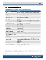
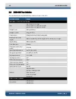
shipped will vary, depending on the customer requirements, the 2000 Series Combined Side Scan Sonar
and Sub-Bottom Profiling System typically includes, as a minimum, the items listed below.
•
2000 Topside Processor
•
2000-DSS Tow Vehicle
•
LCD Monitor (2)
•
Keyboard
•
Trackball
•
Ethernet patch cable
•
AC power cords (4)
•
Video cable (2)
•
Tow cable adapter
•
Software CDs with electronic manuals
In addition to the listed components, the following optional items may be included:
•
Tow cable
•
Test cable
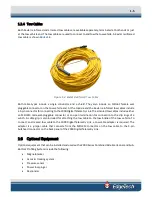
Summary of Contents for 2000-DSS
Page 20: ......
Page 56: ...Figure 4 2 2000 Digital Telemetry Link Electronics Block Diagram...
Page 57: ...Figure 4 3 2000 Digital Telemetry Link Wiring Diagram...
Page 59: ...Figure 4 4 Tow Vehicle Electronic Block Diagram...
Page 60: ...Figure 4 5 Tow Vehicle Interconnect Drawing...
Page 63: ...Figure 4 6 Armored Cable PMI Grip Unterminated Topside...
Page 64: ...Figure 4 7 Test Cable...
Page 77: ...5 13 Figure 5 16 Magnetic Declination Estimated Value Screen...
Page 79: ...5 15 getDeclination CR Figure 5 18...
Page 80: ......
Page 94: ......
Page 96: ......
Page 98: ......

