3-3
3.3
Navigation Interface
The 2000-DSS Combined Side Scan Sonar and Sub-Bottom Profiling System accepts most standard
National Marine Electronics Association (NEMA) 0183 message sentence formats from a connected global
positioning system (GPS) or integrated navigation system.
3.4
Topside Location—Best Practices
The Rack Mount topside should be located and set up in a dry, sheltered area that is protected from
weather and water spray and where the temperature is consistently between 0°C and 40°C (32°F and
104°F). However, in all cases avoid areas of direct sunlight, especially in tropical environments, as heat
buildup could occur and the viewing of indicators could be difficult.
The location of the Rack Mount topside should also enable direct communications with the deck crew
that is handling the tow vehicle. Secure the equipment in place, using tie downs if necessary, near the
required AC power source. Also ensure that there is ample room behind the rack for connecting the cables.
3.5
Rack Mount Topside Connections, Controls, and Indicators
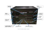
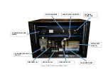
The Rack Mount Topside is composed of the 2000 Topside Computer and the 2000 Digital Telemetry Link.
While reading the descriptions to follow, refer to
components.
3.5.1
Topside Computer Connections
The Topside Processor connections are made using connectors on both the front and back panels, and
include the following:
COM 5 THRU 8:
DB-9 male connector. Available RS-232 ports to connect
additional peripheral sensors/instruments requiring a serial
communication interface.
ETHERNET 1:
RJ-45 connector. Provides the 10/100/000BaseT Ethernet
connection to the 2000 Digital Telemetry link.
ETHERNET 2:
RJ-45 connector. Available 10/100/1000BaseT Ethernet
connection.
USB:
(5) USB connectors. Four USB 2.0 ports two on the back panel
and two on the front. One USB 3.0 port on the back panel
VAC INPUT:
CEE-type AC input In addition, COM5–COM8 serial ports are
available for use as required, each with DB-9 male connectors.
These connectors are located on the back panel.
Summary of Contents for 2000-DSS
Page 20: ......
Page 56: ...Figure 4 2 2000 Digital Telemetry Link Electronics Block Diagram...
Page 57: ...Figure 4 3 2000 Digital Telemetry Link Wiring Diagram...
Page 59: ...Figure 4 4 Tow Vehicle Electronic Block Diagram...
Page 60: ...Figure 4 5 Tow Vehicle Interconnect Drawing...
Page 63: ...Figure 4 6 Armored Cable PMI Grip Unterminated Topside...
Page 64: ...Figure 4 7 Test Cable...
Page 77: ...5 13 Figure 5 16 Magnetic Declination Estimated Value Screen...
Page 79: ...5 15 getDeclination CR Figure 5 18...
Page 80: ......
Page 94: ......
Page 96: ......
Page 98: ......

