
4-28
SECTION 3: SETUP AND ACTIVATION
2000-DSS COMBINED SONAR
0009335_REV_D
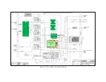
are also included. +5, +12 and -12 VDC power is input on J5 from
the Power Distribution board.
DDC
The DDC board is used in place of the Sonar Interface board for
the 300/600 kHz system.
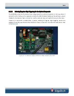
SIDE SCAN
The Side Scan board is a four channel receiver that provides
analog to digital conversion of the received sonar signals which
are input on J1 from the T/R Switch board. The digitized signals
are output on J2 to the Sonar Interface board. Indicators on the
Side Scan board illuminate when signals are being received.
SUB-BOTTOM
The Sub-bottom board is a single channel receiver that provides
analog to digital conversion of the received sonar signals which
are input from the hydrophones on J4 on the electronics bottle
connector end cap. The digitized signals are output on J2 to the
Sonar Interface board. Indicators on the Sub-Bottom board
illuminate when signals are being received.
COMPASS
The Compass board provides heading, pitch and roll outputs to
the USB port of the CPU board.
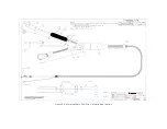
4.3
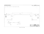
Cables
Outline drawings of the optionally available tow cable and test cable are listed below along with their
corresponding figure numbers.
•
•
Summary of Contents for 2000-DSS
Page 20: ......
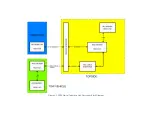
Page 56: ...Figure 4 2 2000 Digital Telemetry Link Electronics Block Diagram...
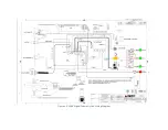
Page 57: ...Figure 4 3 2000 Digital Telemetry Link Wiring Diagram...
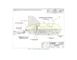
Page 59: ...Figure 4 4 Tow Vehicle Electronic Block Diagram...
Page 60: ...Figure 4 5 Tow Vehicle Interconnect Drawing...
Page 63: ...Figure 4 6 Armored Cable PMI Grip Unterminated Topside...
Page 64: ...Figure 4 7 Test Cable...
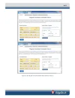
Page 77: ...5 13 Figure 5 16 Magnetic Declination Estimated Value Screen...
Page 79: ...5 15 getDeclination CR Figure 5 18...
Page 80: ......
Page 94: ......
Page 96: ......
Page 98: ......


