5-2
2000-DSS COMBINED SONAR
0009335_REV_D
NOTE:
Remember to always install dummy connectors on the connectors
of the tow cable and the tow vehicle tow cable connector.
5.1.3
Storage
When not in use, all the components of the 2000 Series Combined Side Scan Sonar and Sub-Bottom
Profiling System should be packed in their original shipping containers in the same manner in which they
were originally shipped and stored in a dry area.
5.1.4
Recommended Spares
Spares, such as circuit boards, power supplies, cables, and other critical items should be purchased at the
same time as the system is purchased, as some original equipment manufactured (OEM) components may
change. All spares are optional. For a list of recommended spares at the time of the system purchase,
contact EdgeTech sales.
5.2
Restoring the Operating System to the Hard Drive
The Topside Processor contains a 160-GB hard drive for both the operating system and the application
software. A separate 1-TB hard drive is also included for data recording. An image file of the 160-GB hard
drive is provided on a CD. This CD can be used to completely restore the 160-GB hard drive to its original
shipped factory configuration in the unlikely event of its failure. For instructions on how to restore the
operating system, refer to APPENDIX B: “System Backup and Restore.”
5.3
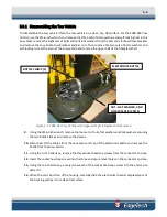
Disassembling and Reassembling the Tow Vehicle
The procedures below describe how to disassemble and reassemble the tow vehicle to access and remove
the electronics chassis. The tools required are a 9/16-inch wrench, a 7/16-inch wrench and a ½-inch allen
key.
WARNING!
High voltages that can cause injury or death are present in
the tow vehicle. Turn off both the Topside Processor and the 2000 Digital
Telemetry Link and disconnect the tow cable before disassembling the
tow vehicle.
Summary of Contents for 2000-DSS
Page 20: ......
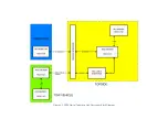
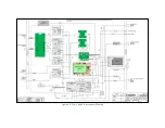
Page 56: ...Figure 4 2 2000 Digital Telemetry Link Electronics Block Diagram...
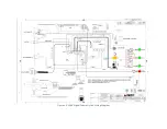
Page 57: ...Figure 4 3 2000 Digital Telemetry Link Wiring Diagram...
Page 59: ...Figure 4 4 Tow Vehicle Electronic Block Diagram...
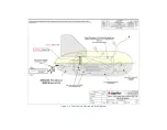
Page 60: ...Figure 4 5 Tow Vehicle Interconnect Drawing...
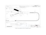
Page 63: ...Figure 4 6 Armored Cable PMI Grip Unterminated Topside...
Page 64: ...Figure 4 7 Test Cable...
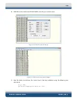
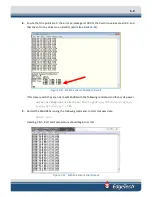
Page 77: ...5 13 Figure 5 16 Magnetic Declination Estimated Value Screen...
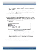
Page 79: ...5 15 getDeclination CR Figure 5 18...
Page 80: ......
Page 94: ......
Page 96: ......
Page 98: ......

