62
5. Parameter Description
Eaton Electric General Inverters DF1 Series
UMXXXXXXXXE February 2020 www.eaton.com
•
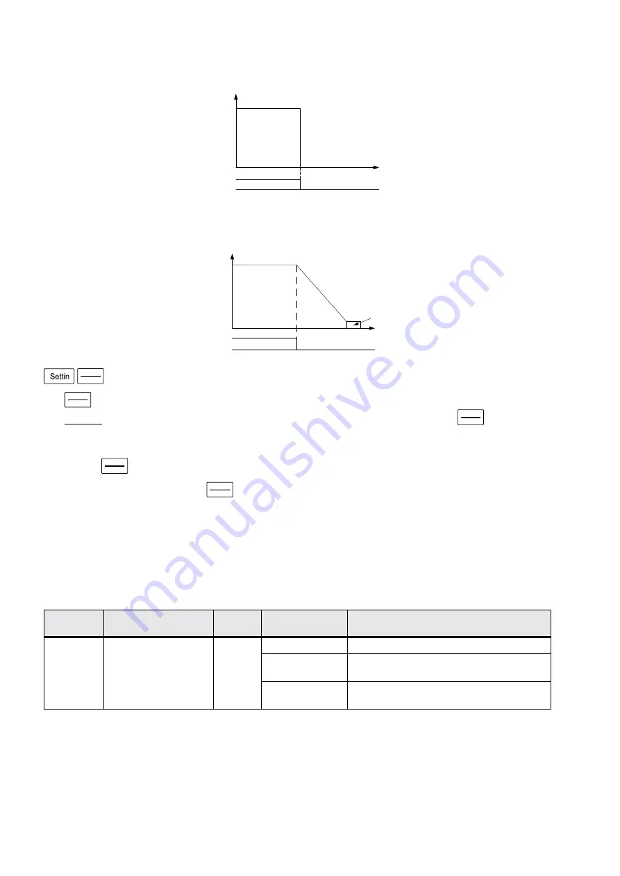
Linear braking(00-13=“1”)
The output of the inverter will follow the acceleration / deceleration curve to decelerate until stop after the stop
signal is accepted.
RESET
STOP
Button function selection
•
RESET
STOP
to stop the operation.(00-14=“1”)
NoticeIn
any modes except the PU and the H2 mode, the motor can be stopped by pressing
RESET
STOP
. The inverter
then displays E0 and all functions of the inverter are disabled. To unlock the state, follow the procedures below:
1. If the start signal is the digital input terminal, it is necessary to cancel the digital input start signal given(Note1);
2. Press
RESET
STOP
button for over 1.0 second to remove E0 state.
•
No matter in which setting, press
RESET
STOP
button for over 1.0 second to reset the inverter after the alarm occurs.
ote:
N
1. In the programmed operation mode, it is not necessary to cancel the start signal.The inverter will run at the section where it
stopped after reset.)
2.After resetting the inverter, the values of the two relays of “electronic thermal relay” and “IGBT module thermal relay” will be
set to zero.
5.1.8 Forward/reverse rotation prevention selection
• Set this parameter to limit the motor rotation to only one direction, and prevent reverse rotation fault resulting from
the incorrect input of the start signal.
ote:
N
It is valid to all start signals.
Parameter
Name
Factory
Value
Setting Range
Content
00-15
P.78
Forward/reverse rotation
prevention selection
0
0
Forward rotation and reverse rotation are both permitted.
1
Reverse rotation is prohibited (Press the reversereference
to decelerate and stop the motor).
2
Forward rotation is prohibited (Press the forward rotation
reference to decelerate and stop the motor).
ON
OFF
Operation
signal
time
O
ut
pu
t
fr
eq
ue
nc
y
(H
Z
)
The motor idling breaking
time
O
ut
pu
t
fr
eq
ue
nc
y
(H
z)
ON
OFF
Operation
signal
Deceleration time
(the time is set by P.8)
linear
braking


