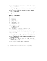


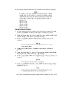


4.5.5 Margin Setup
The Margin Setup procedure shown in Table 4-8 is used to set and display
left and right margins.
Table 4–8:
Margin Setup Procedure
Action
Results
Display
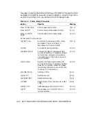
Press (3) ON LINE
Printer goes OFF LINE.
[ O F L]
Press (9) FCT
Printer enters Mode Selection mode.
[.F n c]
Press (5) CPI
Printer enters Margin Setup mode.
[.L r S]
At this point, the options are:
(0) TEST CLR
Exits from Margin Setup to OFF LINE.
[ O F L]
(1) PRG
Counts column position to the left.
[.1 3 2]
to
[.0 0 0]
(2) FORM FEED
Counts column position to the right.
[.0 0 0]
to
[.1 3 2]
(3) ON LINE
Sets left margin.
[.0 0 0]
Factory
Setting
(4) LINE FEED
Sets right margin.
[.1 3 2]
Factory
Setting
(5) CPI LPI
Clears margin to default values (000
and 132 for 10 CPI). Also see Margin vs.
Character Pitch procedure below.
[.L r S]
(6) PAPER REV
Displays current right margin.
[.1 3 2]
(7) FONT
Displays current left margin.
[.0 0 0]
(8) SET TOF
Displays current column position.
[.0 0 0]
NOTE
The display examples given for keys (1) through (8) assume the
printer is set for 10 CPI.
4–38
SETTING COMMUNICATIONS AND PRINT PARAMETERS


