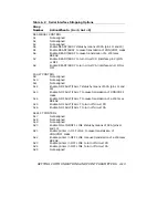
Table 4–1 (Cont.):
Pin Assignments
Pin
Signal
Signal
Direction
Description
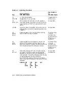
20
CD (DTR)
From Printer
Data Terminal Ready. If so strapped
(A7 IN), data terminal is turned ON
by printer when a positive voltage
level is applied to the pin 20 line, to
indicate printer is ready to accept
data. Straps affect use of CD signal:
A7, A15, A23, A28. See Note 4.
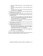
NOTES
1.
BB (RX) is the primary data input line.
It is the line
that carries the serial data from the data source to the
printer.
Data is accepted from this line as long as the
printer is ON LINE, and for one second after the printer
has gone to OFF LINE, to allow for line delays during
satellite communication. A negative level is a mark, and a
positive level is a space. When released, this line should
be in ‘‘Mark’’ condition.
2.
When using XON/XOFF, parity must be set to match the
host.
3.
CC is strap dependent, CB is not strap dependent. Regard-
less of how the printer is strapped, the host may always use
CB to inhibit transmit.
4.
CB must be positive or the lead open-circuit for DC1/DC3
protocol. For this protocol, CA or CD cannot be tied to CB.
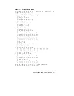
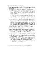
4.3 Configuration Menu
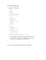
4.3.1 Listing the Parameters
You can get a list of and change all of the user settable parameters
by using the keys on the inner control panel. The nine categories of
parameters are contained in the configuration menu. The subcategories
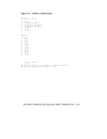
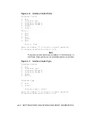
are listed after you select the category. To get a copy of the configuration
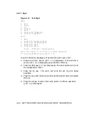
menu, perform the following:
SETTING COMMUNICATIONS AND PRINT PARAMETERS
4–5

