background image

16-36   Operation with the GOES Radio

XL™ Series

NWS:

N

ational 

W

eather 

S

ervice.

PDT:

P

latform 

D

escription 

T

able. 

Note:

Each DCP will have a PDT defined on a computer system at NESDIS. If
the table is not completely defined, then when data is retrieved the error
message “PDT RECORD IS NOT COMPLETE,” will appear. Part of this
table describes the Radio manufacture and model number. For the
Telonics radio, the items must be entered into the PDT table as shown
below.

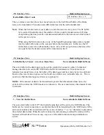
Manufacture:        “Telonics, INC.”
Model Number:    “TGT-1"  

Preamble:

This is a carrier signal sent to the satellite before any data is sent. 

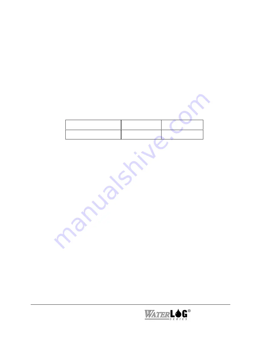
Preamble Type

Short Preamble

Long Preamble

Total Preamble Time

0.98 seconds

7.3 seconds

SHEF Codes:

A two character code that describes the DCP message data type. Common
Shef codes are shown below.

HG

= Stage 

TA

= Temperature Air

VB

= Battery Voltage

Transmission Window:

The scheduled time interval which a DCP can transmit data in the self-timed mode.
This is normally a one-minute window. GOES Radios using the higher baud rates may
be assigned a shorter window. 

UDT:

U

ser 

D

escription 

T

able.

Summary of Contents for H-350XL

Page 1: ...XL Series Models H 350XL H 500XL H 510XL H 522 H 522 Plus Owner s Manual ...

Page 2: ...recy These include all Software Printed Circuit Board Artwork Schematic Diagrams and Technologies applied therein The enclosure encasing the electronics of this instrument may not be opened without written consent of DESIGN ANALYSIS ASSOCIATES INC and any attempt to do so without such written authorization constitutes a breach of contract and will also void any applicable warranty for the product ...

Page 3: ...tion 2 1 2 2 1 Earth Ground Lug 2 2 2 2 2 Pressure Reference Port Vent 2 2 2 2 3 Pressure Port Input 2 2 2 2 4 GOES Antenna Output 2 3 2 2 5 GPS Antenna Connector 2 3 2 2 3 1 Sample Installation for the Conoflow System 2 4 2 2 3 2 Making the Pressure Connection to the H 355 Bubbler 2 5 2 2 6 Bubbler Aux Port 2 6 2 2 7 RS 232 Ports 2 7 2 2 8 Analog Input Section 2 8 2 2 8 1 Analog Input Channels 2 ...

Page 4: ...m Options 5 1 Overview 5 1 5 2 System Setup 5 1 5 3 Time Sync Options 5 5 5 4 Advanced System Setup Options 5 8 Chapter 6 Serial Port Options 6 1 Introduction 6 1 6 2 Serial Port Menus 6 1 6 3 Serial Port Hardware Description 6 6 6 4 Serial Port Functions 6 7 Chapter 7 System Configuration Files 7 1 Overview 7 1 7 2 Configuration Files Menus 7 1 7 3 Sample Configuration File 7 3 Chapter 8 System S...

Page 5: ...s 5 Volt Excitation 11 1 Analog Inputs Overview 11 1 11 2 Analog Menus 11 1 11 3 Analog Options 11 2 11 4 Analog Input Connections 11 4 11 4 1 Analog Inputs and Analog Ground Connections 11 4 11 4 2 Switched 5 00 Volt Reference Excitation 11 5 11 5 Analog Input Setup Examples 11 6 11 6 Two Point Calibration Basics 11 7 Chapter 12 Digital I O 12 1 Digital I O Overview 12 1 12 2 Digital I O Menus 12...

Page 6: ... Set 14 24 14 7 10 Write User Units Slope Command 14 25 14 7 11 Write User Units Offset Command 14 26 14 7 12 Read User Units Slope Command 14 27 14 7 13 Read User Units Offset Command 14 28 Chapter 15 Logging Options 15 1 Logging Overview 15 1 15 2 Logging Options Menu 15 1 15 3 Logging Options 15 2 Chapter 16 Operation with the GOES Radio 16 1 Introduction 16 1 16 1 1 GOES Radio Data Connection ...

Page 7: ...ptions 18 1 18 4 4 To 20 Hardware Connections Wiring 18 4 Chapter 19 Alarm Call Out 19 1 Overview 19 1 19 2 Alarm Call Out Menus 19 1 Chapter 20 Data Card Options 20 1 Data Card Options 20 1 20 2 Data Card Memory Options 20 2 Chapter 21 Operation With the H 355 Smart Gas System 21 1 Introduction to the H 355 21 1 21 2 H 355 Menus 21 1 21 3 H 355 Options 21 2 21 4 H 355 Configuration Drawing 21 7 C...

Page 8: ...Math Functions 23 5 XL Basic Command Summary 23 6 XL Basic Language Descriptions 23 8 Creating XL Basic Programs 23 18 XL Basic Menu Screens 23 18 Example Program 1 23 20 Example Program 2 23 21 Chapter 24 Maintenance Troubleshooting 24 1 Maintenance 24 1 24 2 Troubleshooting 24 1 Appendix A XL Series Specifications A 1 Appendix B Blank B 1 Appendix C Remote Operation Command Mode C 1 ...

Page 9: ...consideration for the access to and use of the PRODUCT extended to you by DESIGN ANALYSIS and to protect the confidential and proprietary information of DESIGN ANALYSIS USER agrees as follows a USER agrees that they will not remove from the exterior of the housing of the PRODUCT any safety warnings or notices of proprietary interest placed thereon by DESIGN ANALYSIS b USER agrees that they shall n...

Page 10: ...ARDLESS OF THE FORM OF THE CLAIM ii EXCEPT FOR THE EXPRESS WARRANTIES ABOVE DESIGN ANALYSIS SPECIFICALLY DISCLAIMS ALL OTHER WARRANTIES INCLUDING WITHOUT LIMITATION ALL IMPLIED WARRANTIES OF MERCHANTABILITY AND FITNESS FOR A PARTICULAR PURPOSE iii UNDER NO CIRCUMSTANCES WILL DESIGN ANALYSIS BE LIABLE FOR SPECIAL INCIDENTAL CONSEQUENTIAL INDIRECT OR ANY OTHER DAMAGES OR CLAIMS ARISING FROM THE USE ...

Page 11: ... a wide temperature range 40EF to 140EF 40EC to 60EC Easy to use program interface and push button keypad Programming does not require an external device i e a laptop computer although all programming and data retrieval can be done through the serial port on a PC keypad and display not available on the H 522 model Provides a bright easy to read display with automatic power shut off after 5 minutes...

Page 12: ...e H 522 Model only Same as the H 522Plus but does not include the built in keypad display Must be programmed through the serial port connected to a PC 1 2 Unpacking the XL Series Data Logger You should have received the following items The XL Series instrument 2 position power terminal block 18 position sensor I O terminal block The XL Series Owner s Manual Wall mounting hardware for the XL 4 10 3...

Page 13: ...ly in non volatile memory There are several ways to retrieve data from the XL The data can be copied to an industry standard ATA FLASH Memory Card The data can be downloaded through the serial port of the XL to the hard disk of a PC via direct connection or modem connection Data can be transmitted through the GOES system for near real time operation The data recorded to the internal memory is stor...

Page 14: ...l 1 5 Advanced Manual Sections There are a few chapters of the manual that are only needed by a small set of users To save paper time and to avoid confusion these chapters may not print using the main PDF file but are still available on the supplied CD or from the web page The following are examples of chapters that may be printed separately Appendix C Remote Operation Command Mode This section di...

Page 15: ... For proper installation you will need The XL mounting hardware Two open end wrenches 7 16 9 16 Model H 350XL Only Small flat blade screw driver Power and communication cables The XL Series Owner s Manual 2 2 Front Panel Description Figure 2 1A shows the wiring panel and illustrates the physical input and output features of the XL Series models H 350XL H 500XL and the H 510XL and briefly describes...

Page 16: ...unit must have a way to measure the atmospheric pressure This port provides that function The user never has to make connections to or service this port Note Model H 500XL and H 510XL only uses this location to secure the wiring panel to the main box using a large hex bolt 2 2 3 Pressure Port Input H 350XL Model only This is the pressurized line input port The user will connect this line to the H ...

Page 17: ...time when power is applied to the unit It will stay on until the time is acquired Once the time is acquired the GPS receiver will turn off and schedule the next update to happen in 25 hours and 15 minutes This non repetitive time prevents the GPS receiver from continually failing due to some external repeated condition When the GPS receiver turns on to re sync the time clock it will try to do so f...

Page 18: ... Conoflow System H 350XL only Figure 2 2 shows a typical H 350XL installation for water depth measurement using the Conoflow gas purge system To install the H 350XL secure it to the wall of the instrument shelter or bench top using the provided mounting hardware This will prevent it from moving or shifting and pulling on the wires and tubing connected to other equipment The H 350XL should be mount...

Page 19: ... system using the H 350XL Install kit which includes all the required hardware You will need a 1 8 NPT male tubing fitting for the pressure input port It is recommended that you use 1 8 copper tubing The proper ferrules must be used to insure there are no leaks The male 1 8 NPT fitting screws into the pressure input port of the H 350XL connector panel shown in Figure 2 1 On the bubbler manifold yo...

Page 20: ...er auxiliary devices are developed to interface with the XL they too will be controlled through the XL menu system This port uses RS 485 hardware for communicating with the auxiliary devices This provides noise immunity and multi drop capability As other devices are used the cable will be daisy chained from one device to the next The H 355 is normally used with the H 350XL because it has the built...

Page 21: ...uire a NULL modem adaptor if connected to a PC a DTE type device The NULL modem cable crosses the communication lines allowing two similar devices to communicate Figure 2 5 shows the pin out for all three ports See the chapter covering the serial ports for complete information on the port operations SERIAL PORT PIN OUT PIN DIRECTION NAME 1 Input Data Carrier Detect DCD 2 Input Receive Data RD 3 Ou...

Page 22: ...0 millivolts This type of sensor should be used with the 500 millivolt range Channels 1 and 2 can also be used in a differential mode The analog inputs use a 20 bit analog to digital converter 2 2 8 2 Analog Grounds There are two analog ground connection points In order to preserve signal integrity it is important to use the analog grounds only for sensors connected to the analog section of the XL...

Page 23: ...duced excitation To a point this will reduce errors in data when the excitation is used If the excitation is being loaded down and some analog input channels are not using the excitation but produce a voltage output on there own then these inputs will have a much greater error 2 2 9 Wind Speed Input AC Frequency Input Pins 8 and 9 of the terminal block provide connection points for a low level AC ...

Page 24: ...t counter input This input is normally used with a tipping bucket rain gauge However it can be used for other counter type of applications also Transient protection is provided for this input to prevent damage from static discharge or over voltage conditions This input is pulled high through a 51K Ohm resistor allowing a switch closure to ground to activate the counter Figure 2 9 shows a simplifie...

Page 25: ...signal based on any of its inputs For example a user may want to connect a temperature probe to the XL and convert the temperature value into a 4 to 20 milliamp output A temperature probe on Analog Channel 1 that produces a 0 to 5 volt output representing 0 to 100 degrees Celsius could easily be setup to produce a 4 to 20 milliamp output that represents the 0 to 100 degrees The XL does not actuall...

Page 26: ...an be configured independently as inputs or as outputs In the input mode the signal has an internal pull up resistor of 51K Ohms This allows a switch closure to ground to activate the input It can also be driven using normal logic levels As an output the drive capability is limited by a 100 Ohm protection resistor The output will still be about 4 0 volts with a 10 0 mA or less load When both pins ...

Page 27: ...can be used as both an SDI 12 sensor and as an SDI 12 data logger In either case these connections are made at the same place The 12V power connection under the SDI 12 section is limited to about one amp so it may be necessary to connect the SDI 12 sensor power line directly to the battery or to main power If several SDI 12 sensors are to be connected to the XL it may be necessary to use an extern...

Page 28: ...nected from the battery This helps prevent loose wires with live voltages accidently come in contact with other I O connection points 2 3 Testing the Installation After hooking up the battery the Power light should begin flashing every 5 to 10 seconds This indicates that the battery is providing 10 volts or more to the XL Press the display On Off button and the display should come on indicating th...

Page 29: ...own sequence from normal mode to low power mode This change will not affect the user operation Rev 3 1 New 24 bit A to D converter for the generic analog inputs and stage sensor The older boards used a 16 bit A to D converter Added differential mode to analog inputs 1 and 2 500 millivolt range added to all generic analog inputs The 12 volt excitation is able to be turned on and off Able to use hig...

Page 30: ...2 16 Hardware Options and Installation XL Series ...

Page 31: ...re is little need for external programming devices such as a laptop computer but remote operations are supported as explained in chapter 4 Note The H 522 has no built in keypad display therefore options in this chapter will not apply to the H 522 3 2 Keypad Display Operation Not available with model H 522 The XL can be fully configured using the built in keypad and display The user can easily move...

Page 32: ... Key The ON OFF key is used to turn the display on and off This key will only turn the display off from the top level of the menu system If the unit is on and in a submenu this key much like the CANCEL key will cause the system to return to the previous menu screen in the menu system hierarchy until the HOME menu screen is displayed at which time pressing the ON OFF key will turn the display off N...

Page 33: ...will always take you to the beginning menu screen III The CANCEL key acts as a NO key on screens looking for a yes or no response For example pressing the CANCEL key on the Erase Data screen will abort the option Arrow Keys The UP DOWN LEFT and RIGHT arrow keys have the following functions I The UP and DOWN arrow keys enable you to scroll from one menu to another When you reach the bottom screen t...

Page 34: ... menu items Each screen represents a unique menu item or system option There are four types of menu screens status screens sub menu header screens option screens and table screens STATUS SCREENS Status screens are normally used to display system information or sensor values The user can select what values or information is used for status screens The system will automatically update some status sc...

Page 35: ... time or the date value Time 12 34 42 Pressing the ENTER key will start the editing process and one of the characters in the brackets will begin to blink The UP and DOWN arrow keys are used to change the blinking character and the LEFT and RIGHT arrow keys are used to move to the next character Pressing the ENTER key will accept the new value or pressing the CANCEL key will keep the original value...

Page 36: ...o The LEFT and RIGHT arrow keys let you to move through the table horizontally and the UP and DOWN arrow keys let you to move through the table vertically While moving through a table pressing the CANCEL key will take the system back to the sub menu header screen used to enter the table Options in the table may be edited as previously explained 3 3 Familiarization The best way to become familiar w...

Page 37: ...ht side of the screen have a sub menu related to the displayed menu Use the RIGHT arrow key to enter the sub menu Use the CANCEL key or the LEFT arrow key to return from the sub menu to the header screen in the main menu PtTemp XX XX BATT XX XX Sensor Input Setup Output Options Data Options Scan Setup System Setup System Status Accessory Setup Stage X XX The shaded screen on the left is a user def...

Page 38: ...d in the logging options table see chapter 15 PtTemp XX XX BATT XX XX Sensor Input Setup Output Options Data Options Scan Setup System Setup System Status Accessory Setup Stage X XX The Sensor Input Setup screen is a sub menu header screen as indicated by the arrow Pressing the RIGHT arrow key will cause the system to enter into the sub menu for all of the sensor input setup options of the XL For ...

Page 39: ...re complex enough that they are described in a separate chapters dedicated to the application PtTemp XX XX BATT XX XX Sensor Input Setup Output Options Data Options Scan Setup System Setup System Status Accessory Setup Stage X XX The Data Options screen is a sub menu header screen The sub menu options allow the user to erase data copy data to an external data card view the data file and see how ma...

Page 40: ...perations ALERT radio operations and several other options will only happen if scanning is enabled PtTemp XX XX BATT XX XX Sensor Input Setup Output Options Data Options Scan Setup System Setup System Status Accessory Setup Stage X XX The System Setup screen is a sub menu header screen The sub menu options under this heading are used to define generic system options such as the time of day date se...

Page 41: ...TT XX XX Sensor Input Setup Output Options Data Options Scan Setup System Setup System Status Accessory Setup Stage X XX The Accessory Setup screen is a sub menu header screen The sub menu options under this header allow the user to controlaccessoryproducts connected to the XL such as the H 355 Bubbler system The H 355 bubbler is discussed in a separate chapter PtTemp XX XX BATT XX XX Sensor Input...

Page 42: ...3 12 Using The Built In Keypad Display XL Series ...

Page 43: ... firmware versions Software Xon Xoff Menu Mode SW Rev 2 04 Command mode on older Versions 300 to 19200 on hardware Rev A to M 300 to 115200 on hardware Rev N up None None None None VT 52 VT 100 None or Hardware Command Mode Menu Mode Basically all options available through the menu interface are also available using the command interface or the built in keyboard and display This chapter focuses on...

Page 44: ...ey or SPACE bar at any time will refresh the current screen At the bottom of each menu screen is an Enter Option prompt When an option key is pressed that allows a system parameter to be changed any additional information for that option will be displayed after the prompt There are two types of system parameter change options first is an option that requires direct keyboard input like a file name ...

Page 45: ... Input Options Used to configure the sensor input parameters such as slopes and offsets for the analog inputs configure the Digital I O modes and SDI 12 sensor configuration D Data Options Allows the user to retrieve data from the unit erase data from memory and perform other internal data and card operations O Output Options Defines if and how the data is stored internaly transmitted via GOES or ...

Page 46: ...4 4 PC Menu Interface Operation XL Series ...

Page 47: ... the options under this menu are big or complex enough that they are explained in their own chapter 5 2 System Setup Built in Menu Structure System Setup Options Menu The order of options in the built in menu differs slightly than that of the PC menu options The text below will follow the order of the PC menu System Setup Time HH MM SS Date MM DD YY Date Fmt MM DD YY Sync Sync Disabled Sync Time N...

Page 48: ...time or to international standard time This is the time used to tag each scan placed in the data file This is a different time clock the one in the GOES radio The GOES radio time clock is normally set automatically by a GPS system and must be set to international standard time The display will be updated each second to allow easy viewing of the current time PC Interface View Built In Display Scree...

Page 49: ...ng system firmware As new versions of software are produced they will be placed on the web at www waterlog com Users can download new or even older versions of the software The file will be a ZIP file that normally will contain two files first is a bin file that is the new firmware and the second is a PDF or text file that will have documentation on it related to the changes in the firmware The us...

Page 50: ...es This makes sure any new variables associated with the new version of firmware is in an acceptable range This actually resets every option to the factory default value 8 Last of all the XL will reload the update cfg file to set up the unit as close to the same mode it was before the update started 9 The user should look over the settings to verify they look as expected 10 To make sure the new ve...

Page 51: ...ve This is normally only used with older GOES radios that did not have GPS capabilities and is not needed with the newer radios This is a status screen used to see when the time clock was last synced It will show the day and month only If it is used then most cases it will show the current day or one day ago which could still be within the last 24 hour period If the date is a few days old then it ...

Page 52: ...o set the date also Notice it is exactly the same as the date option in the menu one level up On the built in menu the normal Date option must be used to see if the time sync is working correctly PC Interface View Built In Display Screen S Sync Sync Disabled Sync Sync Disabled The accuracy of the time clock in the XL may not be as accurate as needed as it may very a couple of seconds per day If a ...

Page 53: ... a GPS receiver This could not be used with the Telonic s radios Logger to GOES This option syncs the logger clock to the GOES clock In this case the GOES radio may or may not be using a built in GPS system In any case the time clock in the GOES radio is more accurate than the logger clock and in any case this will keep the two clocks the same This is commonly used when the GOES radio utilizes a G...

Page 54: ...em Setup Options Advanced System Setup Options Esc to Return W Welcome Message E PassWord Enabled No P PassWord 123 T System Timeout 300 A AutoOff Enabled Yes B Side Button Mode Hold to Update U User Mode Normal D Excitation Delay 0 S Switched Excitation On Always Enter Option PC Interface View Built In Display Screen W Welcome Message SignOn Msg The welcome or sign on message will be displayed on...

Page 55: ... This can be set between 15 and 600 seconds PC Interface View Built In Display Screen A AutoOff Enabled Yes AutoOff Enabled This option is used to enable or disable the auto off feature There may be a time that the user needs to keep the display on all the time so they can watch automatic updates of some system variable On the built in menu pressing the Enter key will toggle this option PC Interfa...

Page 56: ...escription of the different user modes Normal This is the most common used mode and used by over 95 of the users The manual is also based around this mode NOAA This mode is only used with the H 350XL This mode is intended for NOAA when they or one of there contractors is running a PORTS application NOAA uses a special measurement algorithm when measuring water levels This basically is a 3 minute a...

Page 57: ...nge For more information on this mode request the supplement Meteosat Operation FIRELG This mode is intended for use by the Bureau of Reclamation forest and range fire units When the unit is in this mode and the unit is reset to factory defaults several options are set based on their needs and are different from the normal settings PC Interface View Built In Display Screen D Excitation Delay 0 Exc...

Page 58: ...5 12 Miscellaneous System Setup XL Series ...

Page 59: ...orts are an integral part of the operation of the unit they will be discussed in their own chapter 6 2 Serial Port Menus Built in menu structure Serial Port Options Menu System Setup Serial Port Setup BaudRate Com1 9600 BaudRate Com2 9600 BaudRate Com3 9600 StartUp 1 Menu Mode StartUp 2 Menu Mode StartUp 3 Menu Mode Flow Control XXX Char Delay XXX Line Delay XXX Emulation XXXXXX Quiet Mode Off Qui...

Page 60: ...lways 9600 and modbus must be set to 9600 or 19200 baud and is selected under the modbus options menu Some older modems and some cell phone modems work best as slower baud rates such as 1200 Valid baud rates are 115000 57600 38400 19200 9600 4800 2400 1200 and 300 Older units have hardware that only allow baud rates of 19200 and slower The default baud rate is 9600 for all three serial ports PC In...

Page 61: ... unit would not respond Now the serial ports are normally used for point to point communications In this mode it is point to multipoint or one PC communicating to two or more XL series data loggers Normally this mode is only used with an RS232 radio connected to the serial port and the radio link is what provides or allows the multipoint functionality PC Interface View Built In Display Screen F Fl...

Page 62: ...port PC Interface View Built In Display Screen C Character Delay 000 Char Delay 000 This sets a time delay between transmitted characters in milliseconds Some modems normally a radio modem may require this type of control in order to pass valid data through the serial port When using a modem everything may look fine and then all at once it looks like garbage This may be an indication of overflowin...

Page 63: ...revent the XL from echoing back characters received via the serial port for a certain duration of time specified in the quiet mode duration option This option is helpful in preventing endless echo looping in applications such as communicating with a modem The default is off but if a modem is in use then it may be best to turn this on PC Interface View Built In Display Screen D Quiet Mode Duration ...

Page 64: ...dem a DCE type device but will require a NULL modem adaptor if connected to a PC a DTE type device The NULL modem cable crosses the communication lines allowing two similar devices to communicate Figure 2 5 shows the pin out for all three ports SERIAL PORT PIN OUT PIN DIRECTION NAME 1 Input Data Carrier Detect DCD 2 Input Receive Data RD 3 Output Transmit Data TD 4 Output Data Terminal Ready DTR 5...

Page 65: ... 12 Secondary Port Master Mode X New X Auto Print X X X Remote Display From Menu X X X BASIC Print Command X X X Basic Input Command Numeric Only X New X X Was functional in older versions of the firmware 2 09 and older New Now functional in this version of the firmware 2 10 and newer Blank Not a valid option New 1 Com port 5 is only available on the new hardware Hardware Version 3 3 and is only u...

Page 66: ...6 8 Serial Port Options XL Series ...

Page 67: ...way and then minor modifications made for site specific needs The files can be created on the external data card or to internal data memory 7 2 Configuration Files Menus One of the sub menu structures found under the System Setup or Configure System menu is the Configuration Files sub menu These options are used to save and retrieve setup information and to reset the unit back to the factory defau...

Page 68: ...ard using the copy data option When the configuration file is saved to the data card can then be removed and placed in a PC and the file copied to the hard drive or printed for a hard copy of the setup information Other XL series loggers can now be programmed the same as the unit that created the configuration file by using the Setup From CFG File or Load From Memory options listed below PC Interf...

Page 69: ... is the actual setup information Each line is actually a command used when the unit is in the command mode Therefore any single line could be hand typed into the unit when it is in the command mode With close inspection it is possible to relate each command to a user option in the menus It is possible to hand edit this file but the entries must be exact and valid options used or the command will b...

Page 70: ...Units Feet StageOffset 0 00 StageAverageTime 1 TemperatureUnits Deg C RemStageSource None RemStageSlope 1 00 RemStageOffset 0 00 CounterSlope 0 01 SumInterval Daily CounterMode Off CountRateWindowSize 15 CtrDebounceTime 5 FrequencySlope 1 000 FrequencyOffset 0 000 Analog1Slope 1 00 Analog1Offset 0 00 Analog1Samples 2000 Analog1Range 5 0V Analog1DiffMode Off Analog4Slope 1 00 Analog4Offset 0 00 Ana...

Page 71: ...ceModemSource0 None VoiceModemSource9 None AlarmsEnabled No AlarmRetry 0 Alarm1Source None Alarm1Trig Set Pt Alarm1SetPoint 1 000000 Alarm1ResetPoint 0 000000 Alarm1ComMode Direct Alarm1Label Al1 Alarm1Number Alarm1SiteNum 0 Alarm10Source None Alarm10Trig Set Pt Alarm10SetPoint 1 000000 Alarm10ResetPoint 0 000000 Alarm10ComMode Direct Alarm10Label Al0 Alarm10Number Alarm10SiteNum 0 ModbusMode Off ...

Page 72: ...RT20TriggerPoint 1 000 ALERT20HoldOff 15 ALERT20Override 2 000 Logging On LogNewFile None LogDataFmt Normal LogWrap Disabled WrapBlocks 255 LogColumn1Source Date LogColumn1Header MM DD YY LogColumn1Rate 00 15 00 LogColumn1Digits 2 LogColumn1Function NOW LogColumn1StatScrn No LogColumn25Source None LogColumn25Header LogColumn25Rate 00 15 00 LogColumn25Digits 2 LogColumn25Function NOW LogColumn25Sta...

Page 73: ...naryBytes 3 GoesSTColumn1BinaryDigits 2 GoesSTColumn1BinarySigned Signed Mag GoesSTColumn20Source None GoesSTColumn20SHEFCode GoesSTColumn20Rate 00 15 00 GoesSTColumn20Format XX XX GoesSTColumn20BinaryBytes 3 GoesSTColumn20BinaryDigits 2 GoesSTColumn20BinarySigned Signed Mag GoesRRChannel 000 GoesRRRate 00 05 00 GoesRRColumn1Source None GoesRRColumn5Source None AutoPurge Off TimedPurge 0 FNT01 0 F...

Page 74: ...7 8 System Configuration Files XL Series ...

Page 75: ...wing the user to see what is of interest to them Note Depending on the XL Series in use the default status screens settings will be slightly different 8 2 Status Menus Built in Menu Structure Status Screens System Status Battery 12 3 Volts Min Battery 11 6 Max Battery 13 7 System Resets 2 Reset Stat Screens Firmware Ver X XXX Run Checksum Test Hardware Ver X X Serial S XXXXXX Bubble Line Test The ...

Page 76: ... SiteID Serial S 001000 Version 2 10 C Checksum Test M Measure R Reset Batt Max Batt Min System Resets Enter Option 8 3 Status Screen Operations PC Interface View Built In Display Screen Time 09 08 07 Not Available In This Area Of The Built In Menu This is the current system time Notice this updates every second along with some other values on the screen In this menu the time cannot be changed onl...

Page 77: ...Off Not Available In This Area Of The Built In Menu This identifies the current GOES Mode of operation If no GOES radio is connected N A will be displayed PC Interface View Built In Display Screen Fail Safe Ok Not Available In This Area Of The Built In Menu This shows if the fail safe function of the GOES radio is ok or tripped If it is tripped then the GOES radio will not transmit and the reset b...

Page 78: ... value and still not be detected This value is mainly provided as a diagnostic tool to help understand system performance and reliability A high value may indicate a faulty regulator See Reset Status Screens below for more information PC Interface View Built In Display Screen Batt Min 12 34 Batt Min 12 34 Volts Each time the XL measures the battery voltage it checks to see if the current voltage i...

Page 79: ...reen would have the following message Fast Min Mode XX XX PC Interface View Built In Display Screen System Resets 002 System Resets 2 This is a status screen that lists how many times the system has reset A reset can be caused by several conditions low battery and power spikes power glitches and power disconnects are the most common See Reset Status Screens below for more information PC Interface ...

Page 80: ...g properly Consult the factory if this test persistently fails PC Interface View Built In Display Screen M Measure Not Available In Built In Menu Pressing the M key will cause the XL to scan the sensors The sensor data on the screen will be updated with the new values but the data will not be logged to the data card Some data values may update automatically PC Interface View Built In Display Scree...

Page 81: ... awhile Make sure the solar panel is clean If it is normally cloudy for several days may need a bigger battery or solar panel Battery Level Ok Min Batt Level Low Max Batt Level Ok Some Low battery caused system resets Make sure the solar panel is clean If it is normally cloudy for several days may need a bigger battery or solar panel Battery Level Ok Min Batt Level Ok Max Batt Level Ok Some Bad wi...

Page 82: ...ou must use board revision 3 1 or newer The firmware can detect the board revision and if an old board is detected then the menu option to set the 12Volt excitation mode will not be displayed because it has no affect The table below shows the changes to the hardware over the life of the product Board Revision Description Rev 2 1 Original board Rev 2 2 New Power down sequence from normal mode to lo...

Page 83: ...etected and the difference between the MAX and MIN values is displayed on the screen The difference between the MAX and MIN will be small and will not increase too much if the line noise is small but will increase to a larger number if the line noise is significant The displayed value is in the same units as set by the stage Slope Coefficient which defaults to feet When installing a new orifice li...

Page 84: ...8 10 System Status Menus Options XL Series ...

Page 85: ...s a sensor Options here also are used to set the rate data is collected and processed 9 2 Scanning Menus Built in Menu Structure Scanning Options Menu Scan Setup Scanning Off Scan Rate HH MM SS Next Scan HH MM SS Nxt Scan At HH MM SS PC Menu Screen Scanning Options Note The items in bold are not available in the built in menu Scan Options Esc to Return Current Time HH MM SS Next Scan HH MM SS S Sc...

Page 86: ...easurement process will take place When scanning is turned on the XL calculates the best time to start scanning based on the scanning interval and the current time This process tries to keep the logged data or data being sent to the GOES radio synchronized to some logical time interval like on the hour for hourly scans or at 00 15 30 or 45 minute time marks for a 15 minute scan interval This time ...

Page 87: ...ered value For example a 30 second scan rate will automatically turn into a 1 minute scan rate if the measurement process takes 35 seconds to complete PC Interface View Built In Display Screen F Start a New File Not Available In Built In Menu This option causes the unit to start a new data file on the next scan without having to turn scanning off Using this option at the end of a site visit will c...

Page 88: ...9 4 Scanning Options XL Series ...

Page 89: ...This option is in all XL series products 10 2 Stage Temperature Menus Built in Menu Structure Stage Options Menu H 350XL and H 510XL Models Only Sensor Input Setup Stage Setup Stage X XXX Offset 0 000 Stage Units Feet Averaging Time 001 Datum 0 000 PC Menu screen Stage Temperature Options H 350XL and H 510XL Models Only Remote Stage Options All XL Series Products Stage Temperature Setup Esc to Ret...

Page 90: ...ffset 0 00 Offset 0 000 This option screen allows the user to manually enter an offset value to adjust the final stage value in order to obtain a stage value relative to some reference point such as sea level The default offset value of 0 000 can be manually changed by the user or automatically calculated by the H 350XL The following example which refers to Figure 10 1 should make this clear A str...

Page 91: ...the value should get smaller as the water level rises towards the bank The user selects User Def and enters a slope of 2 3067 Using a negative value will cause the H 350XL to display decreasing values as the water level rises The magnitude of 2 3067 is still valid to convert PSI to feet This is done using the standard editing methods to change the slope PC Interface View Built In Display Screen A ...

Page 92: ...tion is shown above PC Interface View Built In Display Screen T Temp Units Deg C PtTemp Units Deg C This option is only available on the H 350 XL as it is the only XL series unit that has a built in temperature sensor used for compensation of the pressure sensor The temperature setup option allows the user to select if temperature values from the built in temperature probe will be displayed and re...

Page 93: ...e Setup RemStage Src None Rem Stage X XXXX Rem Offset 0 000 Rem Slope 1 000 The PC menu structure for the remote stage options is shown above 10 7 Remote Stage Options PC Interface View Built In Display Screen R Remote Stage X XXX Rem Stage X XXX This shows the current value for the remote stage and also allows the user to enter a desired remote stage value and let the XL calculate the offset requ...

Page 94: ...can be manually changed by the user or automatically calculated by the XL as discussed in the Rem Stage section above This offset value is stored in the XL not in the sensor PC Interface View Built In Display Screen 3 Remote Stage Slope 1 000 Rem Slope 1 000 This option screen allows the user to enter a slope multiplier value that will be applied to the remote stage measurement in order to convert...

Page 95: ... Built in Menu Structure Analog Input Options Sensor Input Setup Analog 1 Setup Analog 1 X XXXX Offset 0 0000 Slope 1 0000 A1 Samples 500 Range 5 0 V Differential Md Off Note Menu screens for analog channels 2 3 and 4 are the same as shown above for analog channel 1 except the Differential Mode option is only available for channel 1 and 2 PC Menu Screen Analog Input Options Analog Input Setup Esc ...

Page 96: ... This option allows the user to enter a slope multiplier value that will be applied to the measured voltage in order to convert the value into meaningful units The default value is 1 000 An example would be to convert voltage to wind direction A simple wind direction sensor uses a continuous turn potentiometer excited by the 5 00 volt excitation so the output is 0 to 5 volts for a wind direction o...

Page 97: ...rs that produce a low level output voltage less than 500 millivolts PC Interface View Built In Display Screen X Diff Mode Off Differential Md Off Note This mode is only available on PC board rev 3 1 and newer hardware rev N and newer There are some analog sensors that send back a voltage on a single line that is referenced to ground These are called single ended sensors and are the simplest to wor...

Page 98: ...st seven connections on the twenty pin terminal block are used for analog input functions This includes four analog inputs two analog grounds and one 5 00 volt excitation connection 11 4 1 Analog Inputs and Analog Grounds Connections The four analog input channels are labeled Vin1 to Vin4 There are two analog ground connections In order to preserve signal integrity it is important to use the analo...

Page 99: ... excitation is used If the excitation is being loaded down and some analog input channels are not using the excitation but produce a voltage output on there own then these inputs will have a much greater error 11 5 Analog Input Setup Examples Example 1 A temperature probe with a 0 to 5 Volt output for a temperature range of 40E to 60E Celsius would have the following setup The slope would be calcu...

Page 100: ...e for that temperature The Offset value was calculated using known values At a temperature of 60E Celsius the temperature probe output will be 5 Volts Also at a temperature of 40E Celsius the temperature probe output will be 0 Volts Notice here the minimum voltage is no longer 0 00 and the offset does not equal the minimum sensor value as in the first example In both examples there were two temper...

Page 101: ...ngle The slope is calculated by dividing the rise by the run The rise is the difference between two points on the Y axis Y2 Y1 The run is the difference between two points on the X axis that correlate to the same points on the Y axis or X2 X1 Slope M Y2 Y1 X2 X1 When the values for the two points are manually obtained or manually measured use two points with as big a difference as possible This wi...

Page 102: ...arranging the original equation to solve for the offset and then using known values for the other variables to solve for the offset The known values can come from any single point on the graph for example Y2 and X2 but not Y2 and X1as they are from different point on the graph The offset will not change the angle or slope of the line but vertically shifts the line based on the value of the offset ...

Page 103: ...ructure Digital I O Options Menu The menu for digital I O 2 is the same as below Sensor Input Setup Dig I O 1 Setup Digital I O 1 1 Mode Digital Input Trg Fnt 0 Pulse Length 1000 WarmUp Delay 250 Test Quad Out Built in menu structure Encoder Input and Output Options Menu Sensor Input Setup Encodr Input Setup Enc Out Src None Encodr Val X XXX Encodr Slp 0 01000 The XL can use the two digital I O pi...

Page 104: ...roximately 3 5 volts or higher normally 5 0 volts If the pin value is a 0 the input voltage will be approximately 0 8 volts or less normally 0 0 volts The range between 0 8 and 3 5 is not defined and may be either a 1 or a 0 If the pin is configured as an output the value will be a 1 or a 0 based on whether the output is set to a 1 or a 0 On or Off respectively However the output may be set to a 1...

Page 105: ...igital I O pins Each I O pin can be individually configured as an input or an output The exceptions are the simulated quadrature shaft encoder output mode and the quadrature shaft encoder input mode When using the encoder output mode both I O pins must be set to the Encoder Out mode When using the quadrature input mode both pins must be set to the Digital Input mode Digital Input Input Mode The se...

Page 106: ... would pulse after each scan when the water level was greater than 9 0 feet On For Scan On At Scan Time Mode The selected output will turn on at the beginning of each scan and delay the scanning process for a time specified by setting the WarmUp Delay option After the warm up delay the normal scan process will continue This would be used for applications that require an external device to be turne...

Page 107: ...d would equate to false if it was less than or equal to 10 0 Logical expressions return a value of 1 0 if true and 0 0 if false If the conditional statement is true the output will be triggered set or pulsed high The trigger condition is actually true for any value that is greater than 0 0 and is false for any value that is 0 0 or less This allows for standard math expressions to also be used for ...

Page 108: ...d when the scan process continues on This pauses the scanning process to allow for sensors to warm up or stabilize for proper operation with the XL This value is in milliseconds and the value can range from 1 millisecond to 9 999 seconds The default value is 250 milliseconds An example application where this option could be used is for a motor that needs to be turned on at each scan but requires a...

Page 109: ...et to NONE then the encoder output options is disabled With this set to none the digital I Os can be used for normal digital I O operations or as a shaft encoder input Scanning should be turned off when enabling this option When this mode is enabled and scanning is turned on the system will measure a reference or starting point Each time the unit scans it will measure the selected source and compa...

Page 110: ...circumference each count is 0 01 foot of change and one revolution is one foot of change PC Interface View Built In Display Screen Not Available Using PC Menu Test Quad Out This option allows the user to test the simulated encoder output mode Pressing the Enter key on this screen will prompt the user to Press Up or Down Pressing the up key will cause the XL to simulate 100 counts up whereas pressi...

Page 111: ...ically based on some time interval such as hourly or daily The counters WILL NOT be reset to 0 when scanning is enabled but will maintain any preset value The frequency input is normally used for wind speed sensors but can be used with any sensor that produces a low level AC frequency output The AC signal is normally in the range of 0 15 volts peak to peak centered at 0 00 volts 13 2 Counter and F...

Page 112: ...unter will get reset to 0 00 at the beginning of each day or if the interval is set to Hourly it will get reset to 0 00 at the top of each hour or if the interval set to Scan the value will be reset after each scan This option is also used to enter an initial or offset value This value is not reset automatically when scanning is enabled and should be set by the user to an initial value if needed P...

Page 113: ... Counts value will report the number of counts since midnight The Counts value will be reset to 0 00 every midnight after all scanning and report processes have completed Hourly When set to Hourly the Counts value will report the number of counts since the top of the last hour Scan If set to Scan the Counts value will report the number of counts since the last scan 01 Jan Resets the Counts value t...

Page 114: ...an and goes back in time to the start of the window or in other words this is a sliding window An example of using this option and the CtRate variable follows The user wants to record rain fall and the rate of rain fall The logger is set to log date time totcnt for rain fall and CtRate for the rate of rain fall The scanning is set to 15 minutes and the rate window size is set to 1440 for a one day...

Page 115: ...200 to 255 milliseconds and it would prevent these unwanted tips PC Interface View Built In Display Screen R Reset Countes Reset Counters This option resets both counters to 0 00 and resets the count rate counter 13 4 Frequency Options PC Interface View Built In Display Screen Frequency 0 00 Frequency 0 00 This screen reports the real time converted value for the frequency input channel If a wind ...

Page 116: ...lied if the input frequency is not 0 0 The frequency input is normally used for wind speed sensors and the offset value is a low number that represents the drag of the sensor If there is no wind meaning the raw frequency input is 0 0 the reported value should be 0 0 and not the offset Therefore the offset is not applied when the wind is not blowing ...

Page 117: ...r mode 14 2 SDI 12 Transparent Mode and Full Screen Mode The SDI 12 Transparent options allow the user to talk directly with SDI 12 sensors This mode allows the user to setup test and control SDI 12 sensors All SDI 12 sensors must implement a set of standard commands When using the XL these standard commands can be sent to a sensor using a single key press Extended commands specific to each sensor...

Page 118: ...s the SDI 12 address of the XL when it is used as a sensor PC Interface View Built In Display Screen A Acknowledge Send Ack Cmd This command sends the address followed by the terminator The normal response is the sensor address followed by a Carriage Return and Line Feed If the sensor is not connected or does not respond the XL will respond with Communication Timed Out Refer to the sensor manufact...

Page 119: ...o the sensor manufacturer for proper response to the Verify Command PC Interface View Built In Display Screen M Measure Send Measure Cmd This command sends the address followed by M which is the standard SDI 12 measure command If an error occurs the XL will respond with an error message The response to this command is the time required to make the measurement and the number of values that will be ...

Page 120: ...terface View Built In Display Screen E Edit Extented Ext Cmd 0 This screen is used to enter or edit an extended command It is not necessary to include the sensor address or the terminator they are added automatically Refer to the sensor manufacturer documentation for command options PC Interface View Built In Display Screen F Full Screen Transparent Monitor Mode Not Available In Built In Menu This...

Page 121: ...e This will first search the addresses 0 to 9 and then pauses to see if the user wants to look for sensors using the upper and lower case letters as addresses If a sensor is found it will list its response to the ID command which should include the manufactures name model number of the sensor and version information If two or more sensors use the same address they will not be recognized and the co...

Page 122: ... in this menu would cause the XL to only send the D0 command when the sensor was logged by the XL These menu options allow the user to select the type of measurement command that will be sent for each address For example if the user is using an SDI 12 sensor with address 1 and wants to send the M1 command when the sensor is logged rather than the M command the user would select the address 1 desir...

Page 123: ...creen T No Response Timeout Value 0 000 Timeout Val 0 000 This will be the value used by the XL if an SDI 12 sensor does not respond The default value is 0 00 but this is sometimes valid data and makes it hard to see if the sensor is operating or not The user may select a number that is outside the normal range like 999 for a temperature sensor and now if the recorded value is 999 it is obvious th...

Page 124: ...rs a Serial Port Adrs 0 Port SDI 12 Select which port to use for the selected address SDI 12 commands may be directed out one of the serial ports instead of the standard SDI 12 port PC Interface View Built In Display Screen a A Adrs a Redirect Option Adrs 0 Redirect 0 Select if the primary address will be redirected to a secondary address This is used when multiple measurement types are required f...

Page 125: ...etup Sensor Mode Setup Sensor Mode Enabled Sensor Mode Adrs X SDI Meas Time XXX Par 1 Source XXXXXX Par 9 Source XXXXXX Par 1 Digits 2 Par 9 Digits 2 PC Menu Screen SDI 12 Sensor Mode Options Sensor Mode Setup Esc to Return SDI 12 Sensor Mode Status Enabled A SDI 12 Address 0 T Total Measurement Time 7 1 Parameter 1 Stage B Digits 2 2 Parameter 2 PSI C Digits 2 3 Parameter 3 PtTemp D Digits 2 4 Pa...

Page 126: ...f 0 to 9 but may include other characters like A to Z or a to z The default address for the H 350XL is 0 and the other XL series loggers uses the letter Z as the default address NOTE If the XL is used as the only data logger in the network this address will have no effect on the system and another SDI 12 sensor may have this same address PC Interface View Built In Display Screen T Total Measuremen...

Page 127: ...or this parameter CtRate Use the Count Rate for this parameter AnaX Use analog channel X for this parameter DigI OX Use digital I O X for this parameter Freq Use the frequency reading for this parameter Encoder Use the encoder input value for this parameter Batt Use the Battery reading for this parameter Tscans Use the Tscans reading for this parameter BasicX Use the BasicX reading for this parame...

Page 128: ...municate with an H 310 sensor This is not related to the option that is used to set the address of the XL when it is used as a sensor PC Interface View Built In Display Screen Not Available On The PC Menu H310 Stage X XX This option screen is used to view the current stage reading of the H 310 It may also be used to enter an initial stage value and have the XL automatically calculate the necessary...

Page 129: ...ormally referenced to the ground surface of a well As the water level rises towards the ground level the value reported becomes smaller PSI This uses a slope of 1 00 and report the PSI based on the water level Multiplying by 1 00 will not change the base value which in this case is PSI User Def This will open a new menu screen allowing the user to enter in any slope value desired This could be use...

Page 130: ... 330 Setup SDI 12 Test Adrs 0 H330 Stage X XX H 330 Units Ft CW PC Interface View Built In Display Screen Not Available On The PC Menu SDI 12 Test Adrs 0 This option sets the SDI 12 address the XL will use to communicate with the H 330 or the H 331 encoder This is not related to the option that is used to set the sensor address of the XL when it is used as an SDI 12 sensor PC Interface View Built ...

Page 131: ...ser can change the units to one of two predefined options or select a user defined value The available options are listed below Ft CW This uses a slope of 0 005 and will report water level in feet based on the pulley turning clock wise for an increase in water level Ft CCW This uses a slope of 0 005 and reports water level in feet based on the pulley turning counter clock wise for an increase in w...

Page 132: ...dge a a5 Identify aI aID String 5 Measure aM atttn5 Must use Data Retrieval command to get the data Verify aV atttn5 Data Retrieval aDx a X XX X XX 5 Change Address aAb b5 Extended Commands Read Offset aXRO atttn 5 0 00 Default Write Offset aXWOvalue atttn 5 Read Slope aXRS atttn 5 1 000 PSI 2 3067 Feet Write Slope aXWSvalue atttn 5 ...

Page 133: ... follows a Is the sensor address The following ASCII Characters are valid addresses 0 to 9 A to Z and The H 350XL can be configured to respond to any of the 36 addresses Sensors will be initially programmed at the factory with the address of 0 for use in single sensors systems Addresses 1 to 9 and A to Z can be used for additional sensors connected to the same SDI 12 bus Address is a wildcard addr...

Page 134: ... and verifying the sensor is working properly Since all sensors use the same basic commands it is easy to memorize and use these commands on any sensor 14 7 3 Send Acknowledge Command The Send Acknowledge command returns a simple status response which includes the address of the sensor Any measurement data in the sensor s buffer is not disturbed Command Response a a cr lf Where a Is the sensor add...

Page 135: ...d Response aI allccccccccmmmmmmvvvxx xx cr lf Where a Is the sensor address 0 to 9 A to Z or I Is an upper case ASCII character ll Is the SDI 12 version compatibility level e g version 1 0 is represented as 10 cccccccc Is an 8 character vendor identification to be specified by the vendor and usually in the form of a company name or its abbreviation mmmmmm Is a 6 character field specifying the sens...

Page 136: ...a three digit integer 000 999 specifying the maximum time in seconds the sensor will take to complete the command and have measurement data available in its buffer n Is a single digit integer 0 9 specifying the number of values that will be placed in the data buffer If n is zero 0 no data will be available using subsequent D commands Upon completion of the measurement a service request a cr lf is ...

Page 137: ...mber of parameters returned and their order can be modified by the user Response to a aM1 command Command Response Time Values Description aM1 a0084 cr lf 8 sec 4 Initiate diagnostic pressure and temperature measurement Subsequent Command Response aD0 a xxx xxx yy y XXXXXX YYYYYY cr lf Key Description Units xxx xxx Current Pressure Pounds per Square Inch PSI yy y Current Temperature Centigrade EC ...

Page 138: ...ecksum tests The data generated in response to this command is placed in the sensor s buffer for subsequent collection using D commands The data will be retained in the sensor until another command is executed Command Response Description aV atttn cr lf Initiate verify sequence Where a Is the sensor address 0 to 9 A to Z or V Is an upper case ASCII character ttt Is a three digit integer 000 999 sp...

Page 139: ... and D2 commands are supported or needed Command Response aD0 through aD9 apd d pd d cr lf Where a Is the sensor address 0 to 9 A to Z or D0 D9 Are upper case ASCII characters p Is a polarity sign or and is used to separate values d d Represents a numeric data value If a decimal is not used it is assumed to be after the last digit For example 3 29 23 5 25 45 300 If the number of values returned by...

Page 140: ...if the current address is unknown and only one sensor is connected to the bus A Upper case ASCII character n Is the new sensor address to be programmed 0 to 9 A to Z or NOTE To verify the new address use the Identify Command 14 7 9 Extended SDI 12 Command Set Since not all SDI 12 sensors are the same and may need to be configured differently each sensor may have additional commands for programming...

Page 141: ...mmand To verify the current User Units Slope any other time use the Read User Units Slope command Command Response Description aXWSddd atttn cr lf Write User Units Slope coefficient Where a Is the sensor address 0 to 9 A to Z or XWS Are upper case ASCII characters ddd Is the new User Units Slope value The input format is very flexible Some examples are shown below 20 095 0 195 7 984E 10 167 824E5 ...

Page 142: ...he User Units Offset at any other time use the Read User Units Offset command Command Response Description aXWOddd atttn cr lf Write User Units Offset coefficient Where a Is the sensor address 0 to 9 A to Z or XWO Are upper case ASCII characters ddd Is the new User Units Offset value The input format is very flexible Some examples are shown below 20 095 0 195 7 984E 10 167 824E5 005 9357E 7 500 tt...

Page 143: ...efficient term The value is read from non volatile EEPROM within the sensor and loaded into the sensor data buffer It can be viewed by issuing a D command Command Response Description aXRS atttn cr lf Load sensor buffer with User Units Slope Where a Is the sensor address 0 to 9 A to Z or XRS Are upper case ASCII characters ttt Is a three digit integer 000 999 specifying the maximum time in seconds...

Page 144: ... coefficient term The value is read from non volatile EEPROM within the sensor and loaded into the sensor data buffer It can be viewed by issuing a D command Command Response Description aXRO atttn cr lf Load sensor buffer with User Units Offset Where a Is the sensor address 0 to 9 A to Z or XRO Are upper case ASCII characters ttt Is a three digit integer 000 999 specifying the maximum time in sec...

Page 145: ...ata memory and other logging functions Built in Menu Structure Logging Options Menu Output Options Logging Options Logging On NEW File None Data Fmt Normal Wrap Mode Disabled Report Options Source 1 Date Header 1 Log Rate HH MM SS Digits 1 2 Col 1 Fn NOW Stat Scrn 1 No Notice the options in the far right column have arrows indicating there are more options to the right In this case this is the fir...

Page 146: ... Move left to the previous column This option has no effect on the first column 15 3 Logging Options The options below describe how to setup the logging features of the system The order of the options follow that of the PC menu listed above PC Interface View Built In Display Screen N NEW File None New File None There are some special applications that can be used to automatically download data fro...

Page 147: ... data file which would become larger as time passed causing the transmission to become exceedingly long and the user would have to deal with data that has already been transmitted before PC Interface View Built In Display Screen T Data Format Normal Data Fmt Normal The data stored to internal memory is done so as an ASCII data file There are a few different formats for this file as described below...

Page 148: ...ion is used to allow the unit to continue logging once the data memory fills up by erasing some of the oldest data The wrap process of deleting old data actually happens when the data memory is about half full In most cases this mode is not needed as the data memory will hold several years of data under normal logging conditions and the unit should be cleared out every once in a while anyway The p...

Page 149: ...umn H 350XL Model only PSI Place the PSI reading in the column H 350XL Model only PtTemp Place the Temperature reading in the column H 350XL Model only RemStg Place the Remote Stage reading in the column Counts Place the summation count value in the column TotCnt Place the total counts value in the column CtRate Place the counter rate value in the column AnaX Place analog X value in the column the...

Page 150: ... columns to see exactly which sensors to scan and log As soon as it comes to a column source defined as None it stops the logging process and moves to the next task The default source values for the different XL series products is listed in the table below In many cases the default values will be what is needed for the user application and no changes will be needed Column H 350XL H 500XL H 522 H 5...

Page 151: ...n log a data value based on several scans such as an average a max or a min value Lets say scanning is set to once a minute and the log rate is set to 15 minutes In this case there will be 15 scans for every log value and the average of the 15 values could be logged Now if the log rate is faster than the scan rate then it will log based on the scan rate For example if the log rate is set to 1 minu...

Page 152: ... is set up to log the temperature from a sensor connected to analog channel 1 with a log rate of 15 minutes and a column function of NOW And a second column is setup to log data from the same sensor but the log rate is set to 1 hour and the column function is set to AVG_S The first column will log the current temperature every 15 minutes The second column would average 4 readings and log the resul...

Page 153: ... up the scanned values for the column for the log rate period and log one value at the end of the log rate For example lets say there are two columns set up to report counts The first is set up to report counts on every scan and the second is set with a log rate of 1 hour so it will report only once an hour with a total count for that hour Avg_T This will average every scan regardless of the log r...

Page 154: ...s that happen more often The following Logging Options segment shows column 3 to be logged every hour but the function Alwys is used so it is measured each scan Now look at column 4 that uses a function as a source and is logged every 15 minutes equal to the scan rate If the function uses the stage value as part of its calculation then it will be using a fresh stage value each scan If column 3 fun...

Page 155: ... View Built In Display Screen U Stat Scrn Stat Scrn 1 No This option is used to enable or disable this column to be used as a status screen When the unit is turned on from the front panel it will display a sign on message then data for each column that has been set to be used as a status screen On an H 350XL the defaults for the first two columns are date and time and the option to use these two c...

Page 156: ...15 12 Logging Options XL Series ...

Page 157: ...easons On board revision 3 3 and newer there is a new internal com port used specifically for the GOES radio com 5 that is not available on the outside of the unit In this case com port 2 can still be used by the user for other applications The software can detect the hardware version and automatically adjusts to use the correct com port 16 1 2 GOES Radio Types The XL series data logger is compati...

Page 158: ...this time This radio allowed for 100 and 300 baud transmissions but not 1200 baud rates It also did not utilize GPS time keeping circuitry The accuracy of the built in clock was good enough for the original 100 baud applications and for most of the 300 baud applications Most often this radio was shipped with a secondary GPS time keeping system utilizing a Garmin antenna and receiver Signal Enginee...

Page 159: ...sion The last section of chapter two also discusses the different hardware revisions Several of the GOES options are assigned by NOAA NESDIS United States Department of Commerce National Oceanic and Atmospheric Administration National Environmental Satellite Data and Information Services Other options are user dependant It is the responsibility of the user to apply for and receive approval from NO...

Page 160: ...dom Options Next Txd N A Next Txd At N A Reset GOES Options The following shows the basic GOES options screen when using the PC interface These options are used to set up both self timed and random transmissions PC Menu Screen GOES Main Menu Options GOES Radio Options Esc to Return GOES Radio Type SE 1200 Time To ST Txd Next ST Txd At M Mode Off A Address 00000002 T Time 00 00 00 P Preamble Short ...

Page 161: ... is only used if upgrading from an older style radio to a new unit or one manufacture to a different manufacture SE 100 This is a 100 baud radio from Signal Engineering This did not have GPS capability SE 300 This is a 100 300 baud radio from Signal Engineering This radio did not have the built in GPS receiver but may be equipped with an SDI 12 based GPS receiver The SDI 12 based GPS uses an inter...

Page 162: ...adio H 222 DASE This option is not available using the built in menu PC Interface View Built In Display Screen M Mode GOES Mode Off This option allows the user to define the GOES Radio mode of operation This option should only be turned on after all other GOES options are set as desired The system may not allow the radio to be turned on if the other options are not set properly For example if the ...

Page 163: ...ck is not incrementing every second as expected then the radio has not acquired time from the GPS system this is common at initial power up The radio will not transmit if the time has not been acquired initially or if it has been more than 7 days since the last GPS time sync When using the H 222DA radio the radio will allow the time to be manually set but is best to allow it to sync from the GPS r...

Page 164: ...ay Screen S Self Timed Options Self Timed Options This option opens up the menu structure for configuring all the self timed transmission options This will be described in detail in a following sections titled Self Timed Options PC Interface View Built In Display Screen R Random Options Random Options This option opens up the menu structure for configuring all the random transmission options This ...

Page 165: ...G Reset GOES Options to Default Values Reset GOES Options This option is used to reset just the GOES options to the default values The GOES options are complex and this allows an easy way to start fresh with this section of the XL without affecting any other sections or options of the XL ...

Page 166: ...icate one of the Self Timed options Built in Menu Structure GOES Self Timed Options GOES Options Self Timed Options ST Channel 000 ST Rate 00 00 00 ST Offset 00 00 00 ST Baud Rate 100 ST Window 15 Sec Center Data Yes ST Data Fmt SHEF Data Order SCAN Data First Newest Send SHEF Codes No Append Bat Valu No Extra Data Sets 01 ST Data Options Source 1 None SHEF Code 1 MeasRate 01 00 15 00 Format 1 XX ...

Page 167: ...ned by NESDIS The range for use with the domestic satellites is 001 to 199 and represents a specific frequency for communicating with the satellites If the channel is an even number then it is communicating with the western satellite If the channel number is odd it is communicating with the eastern satellite Channels from 200 and above are for international use PC Interface View Built In Display S...

Page 168: ...elow Center Data In window PC Interface View Built In Display Screen W Self Timed Window ST Window 15 Sec NOAA will assign a window length indicating how much time is allowed to transmit data The default is a 15 second window The options range from 1 minute to a 5 second window The transmission may be set to start the transmission at the beginning of the window default or to center the data transm...

Page 169: ...readable but they take longer to transmit On the other hand Binary data is transmitted quicker but the file will need to be decoded before it can be read If more data is needed then a Binary format may have to be used Refer to the GOES Data Format section below for more details on the SHEF format and the GOES Binary format SHEF Send data in a readable ASCII format For example 15 26 means just that...

Page 170: ... based on scan rate PC Interface View Built In Display Screen N Data Sent First Data First Newest This option defines if the Newest or Oldest data should be sent first Some decode programs only accept the data in one format and not the other PC Interface View Built In Display Screen H Send SHEF Headers Send SHEF Codes No The system uses this option to see if SHEF codes are to be included in the da...

Page 171: ...Sets Extra Data Sets 01 This option is used to set the number of extra data sets to send with each transmission A data set is defined as the data collected for between transmissions Setting this option to 00 would mean do not send any extra or redundant data sets The only data that would be transmitted is the data collected since the last transmission The default value is 01 indicating to the syst...

Page 172: ...01 02 03 04 05 S Source Stage Temp None None None C SHEF Code HG TA R Meas Rate 00 15 00 00 15 00 00 15 00 00 15 00 00 15 00 F Format XX XX XX XX XX XX XX XX XX XX Next Previous Enter Option PC Interface View Built In Display Screen S Source Source 1 None The source option is used to select what data value will be transmitted and in what order Each column normally has a different data source based...

Page 173: ...to Fnt40 Place the results of function xx in the column Note The SDI 12 entries go from address 0 to 9 The parameter is always 1 to 9 The entry SDI 62 would indicate the sensor at address 6 and use the 2 parameter nd PC Interface View Built In Display Screen C SHEF Code SHEF Code 1 XX The SHEF code for each data value may be defined by the user This is normally a two character entry that represent...

Page 174: ...rate such as one second then it will basically just follow the scan rate PC Interface View Built In Display Screen F Format Fmt 01 XX XX The user can choose a data display format for each GOES data value transmitted This option is only valid for the SHEF data not for binary data The format indicates how many digits should be displayed on each side of the decimal point The default is XX XX which is...

Page 175: ...I Mode Esc to Return A All Meas Rates Set To Scan Rate Scan Rate 00 05 00 Column 01 02 03 04 05 S Source Stage Temp None None None R Meas Rate 00 15 00 00 15 00 00 15 00 00 15 00 00 15 00 B Bytes 3 3 3 3 3 D Digits 2 2 2 2 2 P Sign Mode Signed Mag Signed Mag Signed Mag Signed Mag Signed Mag Min Range 1310 72 1310 72 1310 72 1310 72 1310 72 Max Range 1310 72 1310 72 1310 72 1310 72 1310 72 Next Pre...

Page 176: ...s 1 3 Each data value is converted into a Pseudo Binary format consisting of 1 to 4 bytes The more bytes used to represent a value means more precision and range can be preserved at the expense of sending fewer values Each byte in this format uses 6 bits for data one bit always set to a 1 and one bit for parity Now 1 byte with 6 bits used for data gives a range of 0 to 63 so a one byte value in ma...

Page 177: ...he actual range of values that can be properly represented in the GOES pseudo binary format based on the number of bytes selected the digits selected and if the value is positive only or signed The table below shows all the possible combinations To determine which settings to use first determine the range of values the sensor will have and then what precision is needed as far as digits to the righ...

Page 178: ... 262 143 16777 215 0 0063 0 4095 26 2143 1677 7215 32 2048 131072 8388608 3 2 204 8 13107 2 838860 8 0 32 20 48 1310 72 83886 08 0 032 2 048 131 072 8388 608 0 0032 0 2048 13 1072 838 8608 31 2047 131071 8388607 3 1 204 7 13107 1 838860 7 0 31 20 47 1310 71 83886 07 0 031 2 047 131 071 8388 607 0 0031 0 2047 13 1071 838 8607 1 1 1 1 0 1 0 1 0 1 0 1 0 01 0 01 0 01 0 01 0 001 0 001 0 001 0 001 0 000...

Page 179: ...In Built In Menu There is a buffer in the data logger section of the system that is used to collect format and manage the data to be sent to the GOES radio buffer for transmission This status screen indicates how many bytes are in the buffer of the data logger and how many bytes it would hold based on the current menu options such as baud rate window size redundant data etc This is used to see tha...

Page 180: ... 000 RR Rate 00 00 00 RR Baud Rate 100 Tx Fnt 0 RR Data Opts Source 1 XXXXXX Source 5 XXXXXX RR Buffer Cnt 0 Transmit RR Data PC Menu Screen GOES Random Transmit Options Random Options Esc to Return C Channel Number 000 R Transmit Rate 00 00 00 B Random BaudRate 100 A Alarm Condition 0 T Transmit Options F Force Random Transmission Buffer Byte Count 0 Enter Option PC Interface View Built In Displa...

Page 181: ... random transmission should be sent This statement is normally a logical expression that evaluates to being true or false For example ana1 10 0 would equate to true if the value for analog channel 1 is greater than 10 0 and would equate to false if it was less than 10 0 Logical expressions return a value of 1 0 if true and 0 0 if false If the conditional statement is true then a random transmissio...

Page 182: ...mit Options RR Data Options The submenus under this option allow the user to select the data to be sent to the radio and the order Defining the options here is like defining columns in a spreadsheet Source 1 will be the first data value sent to the GOES Radio Source 2 the next and so on Options include Date Time Stage PSI Temp Battery Voltage or any other input option There are a total of five scr...

Page 183: ...eys to view the valid options This is just like setting up the data sources for the timed transmissions PC Interface View Built In Display Screen Buffer Byte Count RR Buffer Cnt 0 This is a status screen that shows how many bytes are in the random transmit buffer of the radio PC Interface View Built In Display Screen F Force Random transmission Transmit RR Data This option causes the system to imm...

Page 184: ... C Transmit Carrier Only Using Self Time Channel Not Available In Built In Menu This option is used to test the RF power output when the signal is not being modulated This test allows for the true power of the transmitter to be measured This will run for 90 seconds or until the user presses a key to stop the transmission Since this is on the self timed channel and is normally used as a local power...

Page 185: ...Time Sync 00 00 00 Last Transmission Duration 0 219 Seconds Fail Safe Status Ok The battery voltage readings give a good indication of how the battery is holding up Mainly look at the difference between the voltage during the last transmission and one of the other readings to see if there is a large difference The current temperature reading should be close to ambient but may be off by a few degre...

Page 186: ...fails and it is normal if the temperature is not at room temperature The temperature reading should be close to ambient temperature PC Interface View Built In Display Screen G GPS Receiver Status Not Available In Built In Menu This option is used to enable or disable the GPS receiver Normally it is only disable to test the transmitter when it is taking a long time to sync If the GPS receiver is di...

Page 187: ... Code 1 HG SHEF Code 2 TA SHEF Code 3 PR SHEF Code 4 MeasRate 1 00 15 00 MeasRate 2 00 15 00 MeasRate 3 00 15 00 MeasRate 4 00 15 00 Format 1 XX XX Format 2 XX XX Format 3 XX XX Format 4 XX XX Also assume that the logging interval is set to 15 minutes Note that with a 15 minute scan interval and a 1 hour transmission rate there will be 4 scans for every GOES transmission Since the Extra Data Sets ...

Page 188: ...ision respectfully The XL will use 3 bytes 18 bits for the main input data values The appended battery voltage will use a single byte 6 bits The time and date will also use only one byte each for seconds minutes hours day and month However date and time are very seldom transmitted through the GOES system and if so mainly for testing purposes The following shows the byte format 1 Byte Value BIT 7 B...

Page 189: ... negative and rSx 204800 1216 56 206072 r in the left position 204800 S in the middle position 1216 x in the right position 56 Total 206072 This is greater than 131071 so subtract it from 131072 206072 131072 75000 Then divide by 100 and change the sign 1 75000 100 750 00 final value Appended battery values are encoded using a single byte To decode the appended battery voltage use the weighted val...

Page 190: ...k 11272192 176128 2752 43 L 3145728 49152 768 12 l 11534336 180224 2816 44 M 3407872 53248 832 13 m 11796480 184320 2880 45 N 3670016 57344 896 14 n 12058624 188416 2944 46 O 3932160 61440 960 15 o 12320768 192512 3008 47 P 4194304 65536 1024 16 p 12582912 196608 3072 48 Q 4456448 69632 1088 17 q 12845056 200704 3136 49 R 4718592 73728 1152 18 r 13107200 204800 3200 50 S 4980736 77824 1216 19 s 13...

Page 191: ... GOES satellite DPS Data Processing System GMT Greenwich Mean Time All DCPs are assigned a time slot in which they are allowed to transmit All DCPs must have an accurate time clock set to GMT in order to make sure they transmit only during the assigned time slot GOES Geostationary Operational Environmental Satellite DCP or DCS systems transmit data to the GOES satellite There are two functional sa...

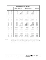
Page 192: ...DT table as shown below Manufacture Telonics INC Model Number TGT 1 Preamble This is a carrier signal sent to the satellite before any data is sent Preamble Type Short Preamble Long Preamble Total Preamble Time 0 98 seconds 7 3 seconds SHEF Codes A two character code that describes the DCP message data type Common Shef codes are shown below HG Stage TA Temperature Air VB Battery Voltage Transmissi...

Page 193: ...5 316 346 13 13 44 72 103 133 164 194 225 256 286 317 347 14 14 45 73 104 134 165 195 226 257 287 318 348 15 15 46 74 105 135 166 196 227 258 288 319 349 16 16 47 75 106 136 167 197 228 259 289 320 350 17 17 48 76 107 137 168 198 229 260 290 321 351 18 18 49 77 108 138 169 199 230 261 291 322 352 19 19 50 78 109 139 170 200 231 262 292 323 353 20 20 51 79 110 140 171 201 232 263 293 324 354 21 21 ...

Page 194: ... 44 73 104 134 165 195 226 257 287 318 348 14 14 45 74 105 135 166 196 227 258 288 319 349 15 15 46 75 106 136 167 197 228 259 289 320 350 16 16 47 76 107 137 168 198 229 260 290 321 351 17 17 48 77 108 138 169 199 230 261 291 322 352 18 18 49 78 109 139 170 200 231 262 292 323 353 19 19 50 79 110 140 171 201 232 263 293 324 354 20 20 51 80 111 141 172 202 233 264 294 325 355 21 21 52 81 112 142 1...

Page 195: ...the transmission was received This should be within the assigned time window In this transmission it was at 18 hours 49 minutes and 03 seconds 163708DE08078184903G51 1NN021EUB00023BCT DZ DY Dc Db Dm Dxj The next byte indicates if the transmission was received properly the G indicates Good Other possibilities are P for parity errors and for unknown errors 163708DE08078184903G51 1NN021EUB00023BCT DZ...

Page 196: ... normally transmit to the western satellite 135 Degrees W 163708DE08078184903G51 1NN021EUB00023BCT DZ DY Dc Db Dm Dxj The next byte is a letter E or W indicating the eastern or western satellite In this case the eastern satellite 163708DE08078184903G51 1NN021EUB00023BCT DZ DY Dc Db Dm Dxj The next two bytes are TBD 163708DE08078184903G51 1NN021EUB00023BCT DZ DY Dc Db Dm Dxj The next few bytes indi...

Page 197: ...the unit successfully updated its time from a GPS system since the last transmission The possibilities are listed below Character Comment Space ASCII Data No time sync since the last transmission Double quote ASCII Data Time did sync since the last transmission Single Quote Binary Data No time sync since the last transmission Lower Case b Binary Data Time did sync since the last transmission The f...

Page 198: ...16 42 Operation with the GOES Radio XL Series ...

Page 199: ...e following menus are used to enable and define what data will be transmitted using the ALERT IFLOWS radio system Up to twenty data values can be monitored and transmitted based on user entered alarm conditions and or on a timed bases Built in Menu Structure ALERT Menus Alert Radio ALERT Radio Off Tx Offset 00 00 00 ALERT Sensor Setup Source 1 None Source 20 None ALERT ID 1 0000 ALERT ID 20 0000 R...

Page 200: ...tions below describe how to setup and use the ALERT system The order of the options follow that of the PC menu listed above PC Interface View Built In Display Screen A ALERT Radio Off ALERT Radio Off This option is used to enable or disable ALERT radio operations The default is Off Valid options are Off Comm 1 Comm 2 and Comm 3 Enabling the ALERT radio also selects which com port it will be used o...

Page 201: ...ion the default range is 20 47 that calculates to a resolution of 0 01 for each count of the ALERT format For example a 15 PSI pressure transducer will cover a range of about 35 feet of water In this case as long as the water level is between 0 00 and 20 47 the value transmitted will be the stage multiplied by 100 to get a number of 0000 to 2047 As the water level increases past the 20 47 mark the...

Page 202: ... 00 0 00 0000 0 01 0 00 0001 0 02 0 00 0002 10 00 0 00 1000 20 00 0 00 20 00 20 46 0 00 2046 20 47 0 00 2047 20 48 20 48 0000 20 49 20 48 0001 34 99 20 48 1451 35 00 20 48 1452 Relationship of the Data Value Base and the ALERT Value Based On Data Values Of 0 00 to 35 00 As stated above the range value defaults to 20 47 and other options are a multiple of that value ...

Page 203: ...ithout the roll over occurring and the base will always be at 0 00 But now the resolution is 0 2 which is normally fine for wind direction PC Interface View Built In Display Screen Divisor Divisor xx xx The divisor is the value the ALERT value must be divided by to convert the ALERT transmitted value back to the original data value The divisor is based on the range value and is listed as a status ...

Page 204: ... transmit rate Max_S This will find the maximum value scanned out of the last X number of scanned values for this column and transmit the results The value of X is the number of scans that happen during the transmit rate interval Min_S This will find the minimum value scanned out of the last X number of scanned values for this column and transmit the results The value of X is the number of scans t...

Page 205: ...o schedule a transmission based on the battery level starting to drop Delta Transmit based on a change in data A transmission is scheduled IF the data changes more than the defined set point value The change can be either an increase or a decrease This could be used to track a changing stream or rainfall Always Always transmit No condition has to be met a transmission is automatically sent on each...

Page 206: ...f time PC Interface View Built In Display Screen F Force Transmission Force ALERT x Txd During the installation it may be desirable to force a transmission in order to test the system Pressing the ENTER key here will cause a transmission to be sent using the ID and data value as described above for the selected column 17 4 Special Cases For ALERT Transmissions An ALERT type non timed transmission ...

Page 207: ... Output Options 4 20 mA Options mA Output X XXX 4 20 Source None Max Value 20 00 Min Value 0 00 PC Menu Screen 4 To 20 Milliamp Options 4 to 20 MilliAmp Output Options Esc to Return Current Milliamp Output Not Enabled S Data Source None H Maximum Level 20 000 L Minimum Level 4 000 Enter Option 18 3 4 To 20 Milliamp Options PC Interface View Built In Display Screen Current Milliamp Output xx xx mA ...

Page 208: ...n S Data Source None 4 20 Source None This selects what sensor is to be simulated as a 4 to 20 milliamp sensor For example if a temperature sensor was connected to analog channel 1 then analog channel 1 would be set as the data source PC Interface View Built In Display Screen H Maximum Level 20 00 Max Value 20 00 This is the maximum value to look for from the data source Continuing on from the exa...

Page 209: ...ch is 1 part in 4096 we can calculate the resolution of the source based on the following equation Input Range 4096 resolution In this example 100 4096 0 02441 degree If the DAC has a resolution of 16 bits then it is 1 part in 65536 In this case the resolution is much greater Input Range 65536 Resolution In this example 100 65536 0 001526 degrees If the hardware revision is 3 3 or newer a 16 bit D...

Page 210: ...signal based on any of its inputs For example a user may want to connect a temperature probe to the XL and convert the temperature value into a 4 to 20 milliamp output A temperature probe on Analog Channel 1 that produces a 0 to 5 volt output representing 0 to 100 degrees Celsius could easily be setup to produce a 4 to 20 milliamp output that represents the 0 to 100 degrees The XL does not actuall...

Page 211: ...ata will be sent based on alarm conditions The data is sent via a modem or RF radios using a very specific format Up to ten data values can be monitored and sent based on user entered alarm conditions 19 2 Alarm Call Out Menus Built in Menu Structure Alarm Call Out Screens Alarm Setup Alarms Enabled No Alarm Retries 0 Individual Setup Source 1 None Source 10 None Trg 1 Always Trg 10 Always Set Pnt...

Page 212: ...ter Option PC Interface View Built In Display Screen A Alarms Enabled No Alarms Enabled No This option is used to enable or disable Alarm operations The default is No PC Interface View Built In Display Screen N Number of Retries 0 Alarm Retries 0 In some cases there may be problems in sending the data For example if the user is using a radio option which may have problems communicating based on a ...

Page 213: ...ons have to be met data is sent automatically on each scan PC Interface View Built In Display Screen T Trigger Point Set Pnt 1 0 0000 The Trigger or Set Point option is used to enter the value used to compare with the actual data to see if data should be sent The section above describes the type of conditions that can be used to trigger a transmission For example if the user wanted to send data ba...

Page 214: ... is for determining how the data is going to sent There are several different options to send the data and are as follows Direct This option sends prints the data directly out Com Port 1 It does not look for any feedback to see if it was received or if an alarm is acknowledged Example of data being sent using Direct Alarm 1 Active at SiteID Stage 999 999 Alarm 2 Active at SiteID Totcnt 999 999 Dir...

Page 215: ...user cannot edit the value when N A is in the brackets which indicates this option is not used for the selected communication option PC Interface View Built In Display Screen F Force Alarm Force Alarm 1 During the installation it may be desirable to force data to be sent in order to test the system Pressing the ENTER key here will cause the data for the selected column to be sent using the ID Tag ...

Page 216: ...19 6 Alarm Call Out XL Series ...

Page 217: ...ture Data Options Menu Data Options Data Memory Ok Data Card Ok View current file MM DD YY HH MM SS Copy Data To Card Copy New To Card Erase All Int Data Erase Int Data File Erase All Card Data Erase Card File Calc DataBytes Free Calc CardBytes Free PC Menu Screen GOES Main Menu Options Data Options Esc to Return Internal Data Status Ok 10 2 Full Data Card Status No Card In Slot C Copy Data To Car...

Page 218: ... power from the system and re powering the unit after about a minute and see if it still displays the error message Consult the factory if the error continues to show up Note On the PC menu the percentage full is also listed PC Interface View Built In Display Screen Data Card Status Data Card OK This is a status message screen for the external data card It has the same messages and meanings as the...

Page 219: ...display the screen will be updated with each new file copied Once the file transfer has completed the external card can be removed placed in other systems for continued data retrieval and then taken back to the office for transferring data to a main computer system and data analysis Data files use the text entered into the Site ID option as the filename Data file extensions always start at 000 and...

Page 220: ...ory or on the external data card When this option is first selected the system prompts the user to select the location of the file The following messages will be displayed Transmit Data Esc to Return I Internal Data D Data Card Transmit Which Data _ Once the user selects the internal data memory or the external data card the system will display all the files on the selected source see the followin...

Page 221: ...Complete File or from Selected Date C D Set File Capture Options Press S To Start Any other key to abort If the file transfer protocol is an XModem transfer then the following screen will be displayed The method to initiate the transfer is dependent on the terminal emulation program in use In Hyperterm use the mouse to select the Transfer option at the top of the window Then select the Receive Fil...

Page 222: ...w data Make sure the data on the card is no longer needed before the data is erased Once erased the data cannot be retrieved The external data card can be erased while scanning is turned on PC Interface View Built In Display Screen F Erase Individual Files Erase Int Data File This option works a little differently when using the built in menu verses the PC menu interface Using the built in menu pr...

Page 223: ...is enabled Using the PC menu a message is displayed allowing the user to select the internal data files or the external data files Once the desired memory location has been selected a list of files for that location will be displayed with an arrow pointing to the first file Use the UP and DOWN arrow keys to select a file to delete and then press the ENTER key to actually delete the file Press the ...

Page 224: ...ike the one listed above Calc DataBytes Free This option is indirectly available from the PC menu See the note below From the built in menu pressing the ENTER key will cause the system to calculate the number of bytes free and available on the data card This option may take several seconds to complete depending on the size of card in use NOTE When using the PC menu interface use the option D Direc...

Page 225: ...al data card the extension will change to a letter followed by the old extension number such as A00 A01 etc If the file already exists on the external data card the letter will be increased by one character value Configuration Files Configuration files will have a CFG file extension The file name will be the same as the site ID of the unit the file was created with Configuration files may also be ...

Page 226: ...ng with the unit NOTE The XL does not support subdirectories and other operations available on a PC It is strongly recommended that data cards used in a PC not be set up with subdirectories or have individual files erased or deleted as some PC systems may try to create a recycle folder which would be considered a subdirectory It is also best to format the cards on the XL and not on a PC as a PC ma...

Page 227: ...gned to replace the Nitrogen tank and regulators used in traditional gas purge systems When combined the XL and H 355 communicate back and forth via the RS 485 link The XL has a submenu dedicated to changing the configuration of the H 355 21 2 H 355 Menus The following is a description of the submenu used for configuring the H 355 Each of these menu items may be changed or edited using the normal ...

Page 228: ...his is a status screen that indicates when the last purge happened This will only be updated if the purge was caused or initiated by the XL If the purge was caused by pressing the button provided on the H 355 then this will not be updated PC Interface View Built In Display Screen Tank Pressure XX XX PSI Tank PSI XX XX This is the current pressure of the H 355 s internal air tank in PSI This value ...

Page 229: ...range is 30 to 120 bubbles per minute using a standard 1 8 inch ID orifice line One reason for changing the bubble rate is to set how quick the system will respond to a rise in stage The following table shows the approximate time needed to react to a one foot rise in stage for the different bubble rates Note this is at a depth of one foot At greater depths the time will increase slightly Bubble Ra...

Page 230: ...bubble rate If the compressor does turn on it is a good indication the purge duration is set long enough to properly purge the line and return to normal operation If the compressor does not turn on after the purge then increase the purge duration by 10 or 20 seconds to make sure the line pressure has stabilized PC Interface View Built In Display Screen Purge Duration Purge Time XXX sec This is the...

Page 231: ...PC Interface View Built In Display Screen Timed Purge Timed Prg XX days This option is used to force a purge every XX days The limits are 00 to 99 days If the option is set to 00 then this option is disabled A value of 01 will cause a purge every day a value of 07 would be once a week and so on The purge will happen immediately following the scan at or just past 12 noon PC Interface View Built In ...

Page 232: ...menu pressing the M key or pressing Enter when using the built in menu will cause the H 355 to perform a purge immediately using the current purge settings If the battery voltage is approximately 11 25 volts or less then the purge will not happen PC Interface View Built In Display Screen N Number of Purges XXX Purged XXX Times This is a status screen that indicates how many times the H 355 has pur...

Page 233: ...te This figure shows the model H 350XL connected to the H 355 bubbler system The H 350XL is the only XL series model with the internal pressure transducer Other models of the XL series data loggers can be used to control the bubbler but would need an external pressure transducer like a H 350Lite connected to the H 355 pressure line and the electrical connection of the H 350 Lite connected to the X...

Page 234: ...21 8 Operation with the H 355 Smart Gas System XL Series ...

Page 235: ...uation If there is an error in the function then a message will prompt the user of the possible position of the error There are a few conditions when the XL does not evaluate the expression and just returns a value For example if a divide by zero occurs in the expression the function will return a value of 99 99 There may be other invalid expressions that result in a value of 99 99 In most cases a...

Page 236: ...g voltage 0 to 5 volts by 72 results in a value between 0 and 360 The second function is the conversion from temperature in degrees C to degrees F where pttemp is the internal temperature probe on the H 350XL reported in degrees C The rest of the function expressions are set to the default of 0 There are two sections to a function first is the function expression and the second is the function val...

Page 237: ...t x based on degrees TAN 30 0 57735 asin x Arc sine x based on degrees ASIN 0 5 30 0 acos x Arc cosine x based on degrees ACOS 0 5 60 0 atan x Arc tangent x based on degrees ATAN 0 5 26 565051 sinr x Sine of x based on radians SINR 1 0 841471 cosr x Cosine x based on radians COSR 1 0 540302 tanr x Tangent x based on radians TANR 1 1 557408 asinr x Arc sine x based on radians ASINR 0 5 0 523599 aco...

Page 238: ...rature in degrees Celsius The following is the actual equation used h377f anaX Convert the voltage on analog channel X from the H 377 thermistor probe to temperature in degrees Celsius This function uses the same equation as the function above but uses the following conversion from degrees C to degrees F tp20b anaX Convert the voltage on analog channel x to a temperature based on the built in volt...

Page 239: ...e x y x does not equal y 1 if true 0 if false x y Is x greater than y 1 if true 0 if false x y Is x greater than or equal to y 1 if true 0 if false x y Is x less than y 1 if true 0 if false x y Is x less than or equal to y 1 if true 0 if false x y Logical AND operation If x does not equal 0 0 AND y does not equal 0 0 then return 1 0 else return 0 0 For example ana1 2 5 ana2 3 5 returns 1 0 if anal...

Page 240: ... current seconds 0 to 59 minutes This is the current minutes 0 to 59 hours This is the current hours 0 to 23 day This is the current day 1 to 31 month This is the current month 1 to 12 year This is the current year 00 to 99 2000 to 2099 stage This is the last measured stage value and is adjusted using the slope and offset Using this variable in a function will not cause a new measurement psi This ...

Page 241: ...ead the older style quadrature shaft encoders If the system is configured for this type of encoder this would cause the encoder to be read and the results to be returned tscans This is the total number of scans since logging started This can be used as a counter or to initialize some variables at the start of scanning sdiAP This will cause the system to scan the sensor at SDI 12 address A and retu...

Page 242: ...next function will be used A single function can be up to 127 characters long but remember this would use the space from three additional functions If a function is greater than the 31 bytes the display will not list the next function as a usable function Notice how function 04 on the following screen is not listed because function 03 has more the 31 characters in its expression Functions Menu 01 ...

Page 243: ...but not so with an function functions are used for counters or running averages where if it was evaluated more than once a scan it could create errors in the returned value and it is not desirable to include the information in the logging report The following example functions will count up on each scan and reset to 0 every day Fnt01 0 Fnt02 if fnt01 day fnt02 1 0 fnt01 day When scanning is starte...

Page 244: ...es F but the desired units are degrees C The probe has an SDI 12 address of 5 with one value returned for temperature Enter an equation that will convert the temperature from degrees F to degrees C Fnt01 sdi51 32 9 5 Fnt01 can now be used as a data source in the log report and the reported value will be temperature in degrees C Math Function Example 2 Rating Curve Most rating curves are developed ...

Page 245: ...es The following equation would be entered for the alarm condition in the random options of the GOES submenu Alarm Condition Stage 20 5 Counts 0 10 If the stage level is higher than 20 5 true and the rain is 0 10 or higher true then a random transmission will be sent Also notice this function is entered under the GOES random menu not in the general purpose functions menu as this function has a ver...

Page 246: ...22 12 Functions XL Series ...

Page 247: ...preter for handling specialized operations outside the normal use of the data logger Since this BASIC interpreter is specific to the XL series of data loggers it is called XL BASIC XL BASIC handles many of the standard BASIC commands but also provides access to the I O and other features of the XL series data logger Basic1 to Basic5 There are five basic programs that can be called any time the sys...

Page 248: ... 5 to the menu option calling the BASIC program These variables are initialized to 0 0 when scanning is enabled and will retain any modifications between scans On return the value will depend on the users BASIC program The basicx Variable This is not a separate variable but is actually an indirect link to one of the normal basic variables 1 to 5 A program can return a value using the variable asso...

Page 249: ...otal count value is returned Countrate Read Write The current count rate on the counter input Encodr Read Write The last measured encoder input value is returned Tscans Read Write The total scans value is returned SdiAP Read Write The last measured value for the selected SDI 12 variable is returned A address 0 to 9 P parameter 1 to 9 FntXX Read Write The last calculated value for function XX is re...

Page 250: ...ly Return H 355 tank PSI if an H 355 is connected linepsi Read Only Return H 355 line PSI if an H 355 is connected purgepsi Read Only Returns H 355 purge PSI setting purgedur Read Only Returns H 355 purge duration setting bubrate Read Only Returns H 355 bubble rate setting Purge Read Only Returns H 355 purge status 0 bubbler communication error 1 request for purge accepted 2 already purging Resets...

Page 251: ...rigonometry Operations Radians sinr x cosr x tanr x asinr x acosr x atanr x Logarithmic Operations log x ln x Misc Function Operations abs x Absolute value of x int x Integer portion of x sqrt x Square root of x int x Integer portion of x h377f anaX Convert voltage on analog channel X to a temperature in degrees f based on math equation for a model H 377 temperature probe h377c anaX Convert voltag...

Page 252: ...EN Conditional program execution END End marker for all programs SENSOR INPUT COMMANDS MEASURE xxxxx Take a new measurement from the selected input VXON Turn on the 5 0 volt excitation VXOFF Turn off the 5 0 volt excitation P12VXON Turn on the 12 volt excitation Hardware Rev N and newer only P12VXOFF Turn off the 12 volt excitation Hardware Rev N and newer only SETDIG1 Set digital I O 1 high SETDI...

Page 253: ...lly as needed This port has no input options INPUT Get numeric values from com port 1 INPUT2 Get numeric values from com port 2 INPUT3 Get numeric values from com port 3 INPUTDELAY x Set how long to wait for input on the serial ports or keypad DIGITS x Set the number of digits to the right of the decimal point to display BUILT IN DISPLAY KEYPAD COMMANDS DISPLAY Send text and data to the local disp...

Page 254: ...x seconds MISCELLANEOUS COMMANDS POKE a d Set system address a equal to d PEEK a Read system address a WRITESDI string Send text and data to the SDI 12 port using SDI 12 timing and retries PRINTSDI string Send text and data to the SDI 12 port one time only no retries GETSDIDATA string Send a measurement command as a text string to the SDI 12 port and collect the data for that command SETTIMEOUT x ...

Page 255: ...m flow should always be documented so it can be easily followed in debugging DELAY Delay milliseconds where is 0 to 65000 Example Delay 1000 Rem delay for 1 0 second GOSUB Go to a subroutine indicated by where is a numeric label at the beginning of a line no alpha characters See the GOTO command for more information on the label limitations There should be a return statement at the end of the subr...

Page 256: ... IF THEN IF condition THEN action Condition is a logical expression that evaluates to true or false If the condition is true then the desired action is executed Valid conditional operators are Operator Example a b a less than b a b a greater than b a b a less than or equal to b a b a greater than or equal to b a b a equal to b a b a not equal to b Example if stage 10 then print stage is greater th...

Page 257: ...time they are used x Ana1 to Ana4 Stage PtTemp psi SDIap FntXX etc VXON Turns the 5 0 volt excitation on VXOFF Turns the 5 0 volt excitation off P12VXON Turns on the 12 volt excitation if it was off Only valid on Hardware Rev N and newer On older revisions the 12 volt excitation was always on P12VXOFF Turns off the 12 volt excitation if it was on Only valid on Hardware Rev N and newer On older rev...

Page 258: ...t buffer for Com 3 PRINT Print text or data to the standard output which is com port 1 Any text listed between quotes will be sent directly to the serial port Example print this is a test This sends the test message out the serial port and terminates the message with a carriage return and a line feed To suppress the carriage return and line feed use a comma at the end of the message Example print ...

Page 259: ... sends a line feed PRINT2 Same as print except the output is to com port 2 PRINT3 Same as print except the output is to com port 3 PRINT4 Same as print except the output is to com port 4 the RS 485 port INPUT Waits for a numeric value to be entered on comport 1 If no input is received within the timeout period defined by the INPUTDELAY command then program execution continues and the variable used...

Page 260: ...ear all text from the display and position the curser at the home position If the display is not turned on before this command is used then the display will be turned on automatically Using this command is an easy way to turn on the display DISPCURSER Position the curser at position where is 00 to 19 This allows a message to be displayed once and some portion of the screen updated as needed withou...

Page 261: ...Example dispopen dispclear display If Raining Press ENT x inkey if x 2 0 then goto 100 dispoff end 100 digits 0 openfile B SERVICE LOG writefile Date date writefile Time time writefile Currently raining closefile dispoff end LEDON Turn on the Error LED Note the led will not turn on if the display is not turned on LEDOFF Turn off the Error LED ...

Page 262: ...t is to the open file CLOSEFILE Closes the file opened using the OPENFILE command H 355 Bubbler Commands SETBUBBLERT x Sets the H 355 bubble rate to value x The bubble rate may be set between 30 and 120 A value less than 30 will result in a bubble rate of 30 and a value greater than 120 will result in a bubble rate of 120 SETPURGEPSI x Sets the H 355 purge pressure in PSI to value x The PSI value ...

Page 263: ...if the address has been redirected The string format for this command is much the same as the print command Example printsdi 0I GETSDIDATA string This command is normally used to send a measurement command as a text string out the SDI 12 port to smart sensors and then collects the data from the sensor and stores it in variables a to i This allows the logger to collect data from sensors that have a...

Page 264: ...ile name that describes the operation of the program This will help when several files reside in the same folder Also the file extension must be BAS When the XL series data logger looks for files to load for basic programs it uses the file mask BAS so only the BAS files are listed XL Basic Menu Screens Menu options are available on both the built in display and on the PC menu interface to load and...

Page 265: ...al 2 Erase all XL BASIC programs currently loaded into internal memory 3 The data logger prompts the user to select a file to load for XL BASIC program 1 4 Using the UP DOWN and ENTER key the user selects a file to load 5 The data logger prompts for files 2 3 4 and 5 in the same manner until all are loaded PC Interface View Built In Display Screen G Get Code From Memory to PC Card Get XL Basic Cod...

Page 266: ...he program These lines are not executed interpreted by the Basic interpreter In the logging options of the H 350XL could have the following columns defined for reporting Date Time SDI11 SDI21 and BASIC1 SDI11 and SDI21 are the shaft encoders used to measure the head and tail gauge levels BASIC1 would call the XL Basic program named xlbasic1 bas which would output the gauge levels to the remote dis...

Page 267: ...the end of the scan This is because the purge will create a lot of noise on the orifice line and this gives the most amount of time from the purge to the next measurement for the noise to dissipate REM Program to purge every 4 scan th REM this value sets the number of scans to make before a purge should be done REM In this example a purge will be done every 4 scans REM If scanning every 15 minutes...

Page 268: ...23 22 XL BASIC Programming Guide XL SERIES ...

Page 269: ...d Feedback from customers is very valuable and greatly aids in the quest for constant product enhancement Please feel free to call the factory for technical assistance and also with solutions you have found to past problems Our experience with pressure transducers has taught us a lot about the problems associated with field installed equipment The following list of problems and possible solutions ...

Page 270: ...em Check all of your plumbing connections with a soapy water solution or a commercial leak detection solution such as SNOOP Because the XL has laboratory quality accuracy even the smallest leak will show up as an error in your data 2 If you have entered a User Unit Slope and or Offset either in your data recorder or in the XL verify they are calculated and entered correctly 3 Verify that the orifi...

Page 271: ... 0 25 µA Pressure Sensor H 350XL Only Accuracy Maximum percent of error in measurement Pressure Less than or equal to 0 02 of full scale output FSO over temperature range referenced to a straight line stretched from zero psi to maximum pressure Temperature Internal temperature 1 C over temperature range Resolution Smallest change detectable in output signal Pressure 1 part in 65 536 0 002 Temperat...

Page 272: ...p for one year from date of shipment Mechanical Data Physical H 350XL Only Enclosure Sealed corrosion resistant fiberglass with clear Lexan window Size 7 0 in wide x 8 5 in long x 4 3 in deep Weight 4 25 lbs Mounting Hardware supplied for wall mounting Physical H 500XL H 522 Enclosure Sealed corrosion resistant fiberglass with clear Lexan window Size 7 0 in wide x 8 5 in long x 4 3 in deep Weight ...

Reviews: