11-2 Analog Inputs / 5 Volt Excitation
XL™ Series
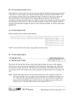
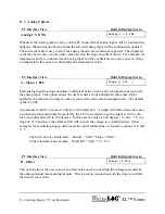
11.3 Analog Options
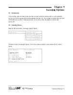
PC Interface View Built In Display Screen
Analog 1: X.XXX
Analog 1 = X.XXX
Whenever the Analog menu is active on the PC menu all four analog inputs will be continuously
updated. When using the built in menu the selected analog input will be continuously updated.
These screens make it easy to see if the analog input(s) are working as expected. The displayed
value may be in volts or some other value based on the slope and offset values. For example, if a
temperature probe is connected to an analog input and the coefficients are set to convert voltage
to temperature, this screen would display the temperature value.
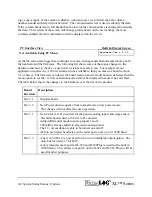
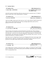
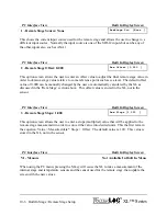
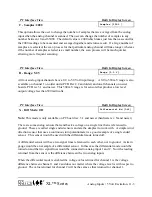
PC Interface View Built In Display Screen
A - Slope: 1.000
Slope [1.000 ]
Each analog input has slope and offset coefficient value used to perform a linear conversion for
the analog input. This option allows the user to enter a slope (multiplier) value that will be
applied to the measured voltage in order to convert the value into meaningful units. The default
value is 1.000.
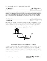
An example would be to convert voltage to wind direction. A simple wind direction sensor uses
a continuous turn potentiometer excited by the 5.00 volt excitation so the output is 0 to 5 volts
for a wind direction of 0 to 360 degrees. In this case the slope is 360 degrees / 5 volts = 72, so a
slope of 72.0 and leave the offset at 0.00 will convert the voltage to a wind direction. Other
examples for calculating slopes, offsets and two point calibrations are found in sections 11.4 and
11.5.
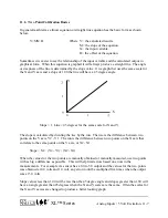
The final value is calculated as: Results = Volts * Slope + Offset
In the wind direction example: Wind Dir = Volts * 72 + 0.0
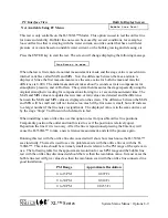
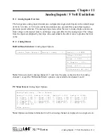
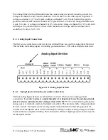
PC Interface View Built In Display Screen
B - Offset
Offset [0.000]
This option allows the user to enter an offset value used in converting the voltage measured by
the analog channel into meaningful units. This is used in conjunction with the slope to perform
the desired conversion.
Summary of Contents for H-350XL
Page 1: ...XL Series Models H 350XL H 500XL H 510XL H 522 H 522 Plus Owner s Manual ...
Page 30: ...2 16 Hardware Options and Installation XL Series ...
Page 42: ...3 12 Using The Built In Keypad Display XL Series ...
Page 46: ...4 4 PC Menu Interface Operation XL Series ...
Page 58: ...5 12 Miscellaneous System Setup XL Series ...
Page 66: ...6 8 Serial Port Options XL Series ...
Page 74: ...7 8 System Configuration Files XL Series ...
Page 84: ...8 10 System Status Menus Options XL Series ...
Page 88: ...9 4 Scanning Options XL Series ...
Page 156: ...15 12 Logging Options XL Series ...
Page 198: ...16 42 Operation with the GOES Radio XL Series ...
Page 216: ...19 6 Alarm Call Out XL Series ...
Page 234: ...21 8 Operation with the H 355 Smart Gas System XL Series ...
Page 246: ...22 12 Functions XL Series ...

