2-12 Hardware Options and Installation
XL™ Series
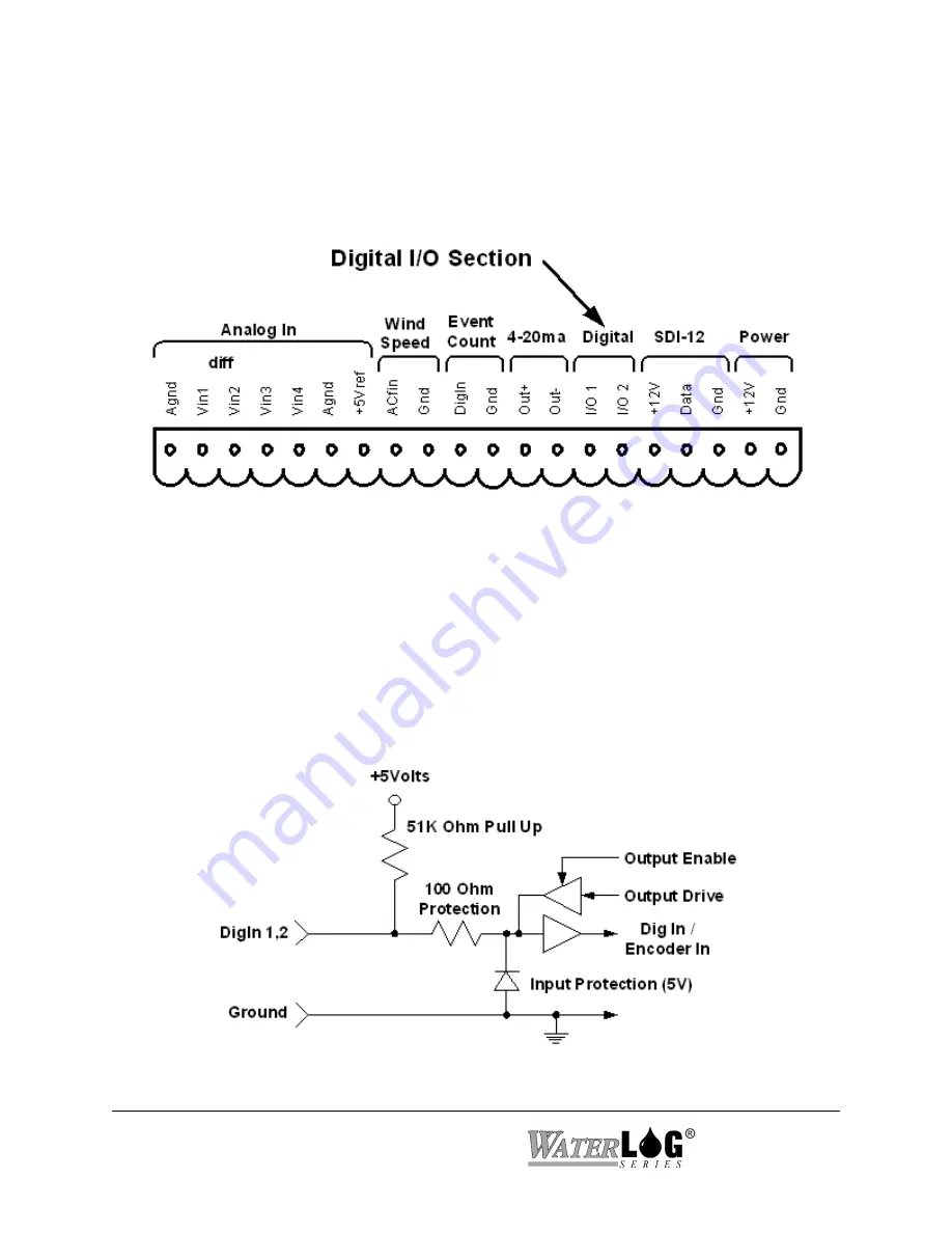
Figure 2-12 Digital I/O Section
Figure 2-13 Basic Digital I/O Schematic
2.2.12 Digital I/O 1 and 2
Pins 14 and 15 of the terminal block provide connection points for the two digital I/O signals.
Notice there is no specific ground point for these signals. Use the digital ground pin of the event
counter or the SDI-12 ground.
Do not use the analog grounds
.
The two digital I/O signals can be configured independently as inputs or as outputs. In the input
mode, the signal has an internal pull up resistor of 51K Ohms. This allows a switch closure to
ground to activate the input. It can also be driven using normal logic levels. As an output, the
drive capability is limited by a 100 Ohm protection resistor. The output will still be about 4.0
volts with a 10.0 mA or less load. When both pins are configured as inputs, they may be used as
a quadrature shaft encoder input. The two digital signals can also be used to simulate a
quadrature shaft encoder. Figure 2-13 shows a simplified schematic of how these pins are
configured.
Summary of Contents for H-350XL
Page 1: ...XL Series Models H 350XL H 500XL H 510XL H 522 H 522 Plus Owner s Manual ...
Page 30: ...2 16 Hardware Options and Installation XL Series ...
Page 42: ...3 12 Using The Built In Keypad Display XL Series ...
Page 46: ...4 4 PC Menu Interface Operation XL Series ...
Page 58: ...5 12 Miscellaneous System Setup XL Series ...
Page 66: ...6 8 Serial Port Options XL Series ...
Page 74: ...7 8 System Configuration Files XL Series ...
Page 84: ...8 10 System Status Menus Options XL Series ...
Page 88: ...9 4 Scanning Options XL Series ...
Page 156: ...15 12 Logging Options XL Series ...
Page 198: ...16 42 Operation with the GOES Radio XL Series ...
Page 216: ...19 6 Alarm Call Out XL Series ...
Page 234: ...21 8 Operation with the H 355 Smart Gas System XL Series ...
Page 246: ...22 12 Functions XL Series ...


