background image

63

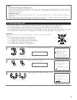
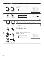
MODE :

DSP

: The analog input signal is converted into a digital signal and undergoes DSP processing.

System Setup settings (speaker configuration, channel delay, etc.) are reflected in the same way as for other input signals.
The surround playback mode button functions.

ANALOG

: The analog input signal is played without DSP processing.

SW and center channel: Down-mixing is conducted by the analog circuit. Surround and surround back channels: Not
output if “No” is selected at the speaker configuration. Channel delay: Not reflected.

S. Back :

Set when MODE is set to “DSP”. Select according to the specifications of the player being used. Also refer to the player’s operating
instructions.

NOT USED : Select when neither SBL or SBR is connected.
SB (SBL)

: Select when only one surround back channel (SBL) is connected.

SBL/SBR

: Select when two surround back channels (SBL and SBR) are connected.

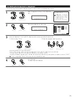
Surr. B :

Select according to the specifications of the player being used. Also refer to the player’s operating instructions.

NOT USED : Select when Surround B is not connected.

The Surround A input signal is output to the Surround B output connector.

USED

: Select when Surround B is connected. The playback in the MULTI CH DIRECT and MULTI CH IN is only possible when

MODE is set to “DSP”.

Surr. Sp :

Set when MODE is set to “ANALOG”. Select according to the specifications of the player being used. Also refer to the player’s operating
instructions.

Surr. A

: Select when using surround speakers A.

Surr. B

: Select when using surround speakers B.

Surr. A+B

: Select when using both surround speakers A and B.

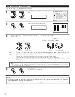
SW Level :

Select according to the specifications of the player being used. Also refer to the player’s operating instructions.
Set the level of playback of the analog input signal connected to the Ext.In Subwoofer.
+15dB (default) recommended. (0, +5, +10 and +15 can be selected.)

INPUT ATT. :

Set when MODE is set to “DSP”.
If the OVER LOAD indicator is displayed on the fluorescent tube, select “–6 dB”.

• The items to be set differ as described below according to the selected input jack and the “Mode” selection.

Mode

S. Back

Surr. B

Surr. Sp

SW Level

Input ATT.

EXT. IN-2 (6 CH)

EXT. IN-1 (10 CH)

DSP

ANALOG

NOT USED, SBL/SBR, SB (SBL)

NOT USED / USED

NOT USED / USED

Surr.A / Surr.B / Surr.A+B

0, +5, +10, +15 dB

0, +5, +10, +15 dB

OFF, –6 dB

DSP

ANALOG

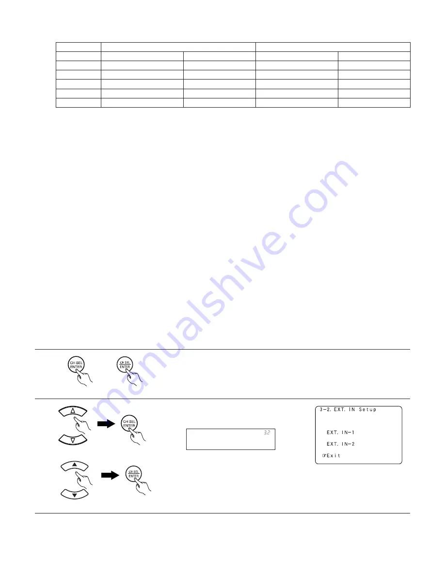
Surr. A / Surr. B / Surr. A+B

0, +5, +10, +15 dB

0, +5, +10, +15 dB

OFF, –6 dB

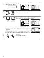
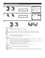
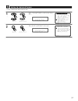
5

Enter the setting.
The EXT.IN Setup screen reappears.

Select “Exit” and press the ENTER button to return
to the Audio Input Setup menu screen.

6

E x i t

* E X T . I N   S e t u p

(Main unit)

(Remote control unit)

(Main unit)

(Remote control unit)

(Main unit)

(Remote control unit)

Summary of Contents for AVC-A1XVA

Page 1: ...you take maximum advantage of all the features the AVC A1XVA has to offer read these instructions carefully and use the set properly Be sure to keep this manual for future reference should any questi...

Page 2: ...with items such as newspapers tablecloths curtains etc No naked flame sources such as lighted candles should be placed on the apparatus Attention should be drawn to the environmental aspects of batter...

Page 3: ...Ger t eine l ngere Zeit nicht verwendet werden soll trennen Sie das Netzkabel vom Netzstecker D brancher le cordon d alimentation lorsque l appareil n est pas utilis pendant de longues p riodes Disinn...

Page 4: ...REFT HET RECYCLEREN Het inpakmateriaal van dit product is recycleerbaar en kan opnieuw gebruikt worden Er wordt verzocht om zich van elk afvalmateriaal te ontdoen volgens de plaatselijke voorschriften...

Page 5: ...crossover frequency individually for the different channels 56 2 6 Selecting the Surround Speakers for the different surround modes 57 2 7 Setting the THX Audio Setup 1 Setting for using a THX Ultra2...

Page 6: ...sing the Remote control unit 153 154 2 Adjusting the tone from the Main unit 154 155 2 Using the Network Audio Function Internet radio function 155 Music server function 155 System requirements 156 15...

Page 7: ...lanation purposes Noise or disturbance of the picture may be generated if this unit or any other electronic equipment using microprocessors is used near a tuner or TV If this happens take the followin...

Page 8: ...ty surround sound from sources such as DTS encoded CDs DVDs with DTS soundtracks and DVD Audio discs that provide DTS soundtracks 5 DTS ES and DTS Neo 6 The AVC A1XVA also supports the DTS ES 6 1 matr...

Page 9: ...res dedicated sub windings and high current ultra stable DC rectifiers and high rated smoothing storage capacitors with a tremendous 132 000 F total storage capacity 5 Pure Direct Mode According to th...

Page 10: ...n 3 Digital Audio Delay Function For optimum picture and sound synchronization the AVC A1XVA features an adjustable digital audio delay function variable from 0 200 milli seconds 4 Adjustable Crossove...

Page 11: ...control unit No power is supplied from this outlet when this unit s power is at standby Never connect equipment whose total capacity is above 100 W NOTES Only use the AC OUTLET for audio equipment Ne...

Page 12: ...in the same way AUDIO VIDEO MONITOR OUT Connect the TV s video input jack VIDEO INPUT to the MONITOR OUT jack using a 75 ohms video coaxial pin plug cord VIDEO Note on connecting the digital input jac...

Page 13: ...eo input jack S IN to the VCR 2 OUT jack using S Video jack connection cords Connect the third and fourth video deck to the VCR 3 and VCR 4 jacks in the same way S VIDEO S VIDEO S VIDEO S VIDEO Connec...

Page 14: ...itor DVD IN jacks Connect the DVD player s component color difference video output jacks COMPONENT VIDEO OUTPUT to the COMPONENT DVD IN jack using 75 ohms coaxial video pin plug cords In the same way...

Page 15: ...A1XVA cannot be controlled by another device via the HDMI connector The audio signals from the HDMI connector including the sampling frequency and bit length may be limited by the equipment that is c...

Page 16: ...ble Note on connecting a HDMI DVI The table below indicates the compatibility of connections between the HDMI DVI D output connector of the AVC A1XVA and monitors that support HDMI DVI D 24P DVI D cab...

Page 17: ...n is 480i interlaced standard definition video NTSC format for North America or 576i interlaced standard definition video PAL format for Europe and other countries To set the video conversion function...

Page 18: ...yer or a multi channel Super Audio CD player or other future multi channel sound format decoder When making connections also refer to the operating instructions of the other components L R L R L R L R...

Page 19: ...jacks TRIGGER OUT Turn the DC 12V voltage on and off for the individual functions and surround modes For details see Setting the Trigger Out See pages 106 107 CONTROL terminal These terminals are use...

Page 20: ...of DVD Audio discs and other multi channel sources is possible by connecting the AVC A1XVA to a DENON DVD player equipped with a DENON LINK connector using the connection cable included with the DVD...

Page 21: ...terface so when connecting a video device connect the video signals as well Assign the IEEE1394 input the input source See page 67 DVD player NOTES Do not use an IEEE1394 cable to connect the AVC A1XV...

Page 22: ...t flows when the temperature surrounding the unit becomes unusually high or when the unit is used at high output over a long period which results in an extreme temperature rise When the protection cir...

Page 23: ...other components IN L L R R L R L R Connection jack for subwoofer with built in amplifier subwoofer etc SURROUND SPEAKER SYSTEMS A CENTER SPEAKER SYSTEM FRONT SPEAKER SYSTEMS Precautions when connect...

Page 24: ...NAMES AND FUNCTIONS Front Panel For details on the functions of these parts refer to the pages given in parentheses 4 3 2 1 0 q w e r t y u i o 5 6 7 8 9 0 7 9 1 2 5 4 2 6 8 0 3 7 5 3 6 4 2 1 3 4 5 8...

Page 25: ...29 0 MultEQ XT indicator 133 1 STANDARD button 143 2 HOME THX CINEMA button 140 3 9CH STEREO button 152 4 DSP SIMULATION button 152 5 SYSTEM SETUP button 28 6 CH SELECT ENTER button 28 137 7 SURROUND...

Page 26: ...lights when each decoder is operating u MASTER VOLUME indicator This displays the volume level The Setup item number is displayed in System Setup i IEEE1394 indicator This lights during playback in a...

Page 27: ...118 HOME VIDEO SELECT button 117 133 Remote control signal transmitter 116 INPUT MODE SELECTOR button 129 NIGHT button 145 SPEAKER button 134 TEST TONE button 137 Tuner system buttons 118 CH SELECT E...

Page 28: ...em setup items and default values set upon shipment from the factory 1 Auto Setup Room EQ Auto Setup Room EQ Default settings 1 Auto Setup Room EQ Setup 2 Direct Mode Setup 4 Set the ON OFF setting of...

Page 29: ...0 dB Surround L A 0 dB Crossover Frequency Set the frequency Hz below which the bass sound of the various speakers is to be output from the subwoofer 5 FIXED THX Page 49 50 2 Subwoofer Setup This sele...

Page 30: ...Hz below which deep bass appearing in the main channels will be routed to the ZONE2 subwoofer 5 80 Hz Page 85 2 Subwoofer Mode This selects the subwoofer used in ZONE2 for playing the low base sound...

Page 31: ...ets the volume level upon switching on the power of each zone Mute Level This sets the amount of attenuation of the audio output when each zone is muted Volume Level This sets whether the output level...

Page 32: ...ory for the different surround modes so they are set automatically when the surround mode is selected A A B B A A B B SB SB SB SB Using A only Multi surround speaker system Using B only Single surroun...

Page 33: ...area For optimum effectiveness measurements should be performed at six or more points Move the microphone successively within the listening area surrounded by the speakers as shown on the diagram bel...

Page 34: ...xtra Setup only when you want to change this arrangement III Check the results of the speaker detection IV Speaker system measurement items q Speaker Configuration This sets the speaker bass reproduct...

Page 35: ...C A1XVA to a TV projector or other monitor I Connecting the microphone for Auto Setup 1 Connect the microphone for Auto Setup to the Setup Mic jack on the front panel of the unit 2 Mount the auto setu...

Page 36: ...t Auto Setup AutoSet RoomEQ Setting the Auto Setup Room EQ 1 1 1 Setting the Auto Setup 1 Select Auto Setup at the Auto Setup Room EQ menu Main unit Remote control unit Auto Setup AutoSet RoomEQ 2 Dis...

Page 37: ...control unit Channel Setup Extra Setup 3 Choose the setting you want to change then press the ENTER button to switch to the setting screen For instructions on making the Channel Setup settings see pa...

Page 38: ...conditioner or any other device that makes noise and take the measurements with the room as quiet as possible Measurement is canceled when MASTER VOLUME is operated while the Auto Setup is performed M...

Page 39: ...Main unit Remote control unit Main unit Remote control unit 2 q The screen shown at the right appears once the measurements for the main listening position are completed Next the measurements for the...

Page 40: ...Remote control unit Calculate 7th Position The amount of time required for the analysis depends on the number of speakers and the number of measuring points The greater the number of speakers and mea...

Page 41: ...easurements have been made using the measurement microphone speakers with a built in filter such as subwoofers might be set with a value that differs from the physical distance because of the internal...

Page 42: ...le errors occur use the cursor left and right buttons to check the contents Check that the pertinent speakers are properly connected The speaker polarity is connected in reverse If multiple errors occ...

Page 43: ...the Room EQ Setup screen Main unit Remote control unit SurMode ALL Room EQ Setup 3 Select ALL or Assign ALL Sets the Equalizer for all surround modes Assign Sets the Equalizer individually for each s...

Page 44: ...Room EQ when the surround mode is Direct or Pure Direct 2 Display the Direct Mode Setup screen Main unit Remote control unit 3 Select ON or OFF Main unit Remote control unit 4 Enter the setting The A...

Page 45: ...other than the included one for measurements when performing the auto setup procedure The microphone included with the AVC A1XVA is a measurement microphone designed specifically for use during the a...

Page 46: ...control unit Parameter Check AutoSet RoomEQ Sp Config Check ParameterCheck 3 Select the items Main unit Remote control unit 4 Press the ENTER button and display the verification screen For instructio...

Page 47: ...reappears Exit EQ Chk Audyssey 11 Select Exit and press the ENTER button at the EQ Parameter Check screen The Parameter Check screen reappears Exit EQ Check Main unit Remote control unit Main unit Rem...

Page 48: ...screen Speaker Setup System Setup Main unit Remote control unit Main unit Remote control unit 2 If the Auto Setup procedure has already been performed there is no need to make this setting Perform th...

Page 49: ...not according to the actual size of the speaker but according to the speaker s capacity for playing low frequency bass sound below the frequency set for the Crossover Frequency signals If you do not k...

Page 50: ...to ON will yield the best results When Front is set to Small Subwoofer is automatically set to Yes and when Subwoofer is set to No Front is automatically set to Large 2 2 Setting the low frequency dis...

Page 51: ...Setup Meters Feet Delay Time Input the distance between the listening position and the different speakers to set the delay time for the surround mode Two surround back speakers are required to use the...

Page 52: ...1 m 1 ft or 0 01 m 0 1 ft When Yes is selected for Default then press the cursor left button to reset to the default values Please note that the difference of distance for every speaker should be 6 0...

Page 53: ...s produced from the speakers to adjust the level The level can also be adjusted directly from the Remote control unit For details see pages 137 138 The level of each channel should be adjusted to 75 d...

Page 54: ...SCREEN SUPER STADIUM ROCK ARENA JAZZ CLUB CLASSIC CONCERT MONO MOVIE VIDEO GAME and MATRIX When using either surround speakers A or B or when using surround speakers A and B at the same time be sure t...

Page 55: ...Crossover Frequency screen Fixed THX Crossover Freq Fixed THX Set to the THX rated 80 Hz crossover frequency Variable 40 60 80 90 100 110 120 150 200 250 Hz Set as desired according to your speakers...

Page 56: ...r Freq 3 Select the frequency Front 100Hz Crossover Freq NOTES If LFE THX is selected at 2 2 Subwoofer Setup the frequencies can only be selected for speakers set to Small at 2 1 Speaker Configuration...

Page 57: ...rs A and B are used At this screen preset the surround speakers to be used in each surround modes 3 q To select the surround mode w To select the surround speaker A When surround speakers A is used B...

Page 58: ...d seems too strong Set Boundary Gain Compensation to ON This activates a filter that gently reduces very deep bass below 55 Hz to provide the flattest overall deep bass response Select ON or OFF accor...

Page 59: ...X Audio Setup screen and press the ENTER button SB Sp Position THX AudioSetup 2 Select the settings according to the distances of the two surround back speakers See page 51 Main unit Remote control un...

Page 60: ...the digital input jack Select from among COAX 1 to 6 OPT 1 to 6 Select OFF for input sources for which no digital input jacks are used It is not possible to select the same digital input jack for diff...

Page 61: ...connect the output of the component connected to the OPTICAL 3 OUT jack on the AVC A1XVA s rear panel to any jack other than the OPTICAL 3 IN jack Do not connect the output of the component connected...

Page 62: ...ct the input terminal w Switch to the setting screen 4 Select the item to be set use the cursor button to the up and down then select the parameter use the cursor left and right buttons EXT IN Setup A...

Page 63: ...CH DIRECT and MULTI CH IN is only possible when MODE is set to DSP Surr Sp Set when MODE is set to ANALOG Select according to the specifications of the player being used Also refer to the player s op...

Page 64: ...screen Input Func Lev Audio In Setup TUNER 0dB Input Func Lev q Select the input source w Adjust the level The level can be adjusted between 12 dB and 12 dB in units of 1 dB 3 When Yes is selected for...

Page 65: ...switches to the character input screen TUNER Rename TUNER Example When TUNER is selected and the cursor left and right buttons are pressed Main unit Remote control unit Main unit Remote control unit...

Page 66: ...n press the cursor left button to reset to the default input source name Rename Clear Rename TUNER Default Yes Rename TUNER 7 Once all the characters have been input press the ENTER button The Functio...

Page 67: ...In this case the connection information is cleared when the power of the connected device or the AVC A1XVA is turned off so the selection procedure must be performed again DVD 3910 DVD IEEE1394Assign...

Page 68: ...the device OFF Select this if you do not want to automatically play the device 3 NOTE In some cases settings may be required on your player Also refer to the player s operating instructions 4 Enter t...

Page 69: ...VI D If the same HDMI or DVI D input terminal is selected the setting for the input source that was previously assigned switches to NONE Select NONE for input sources for which both the HDMI and DVI D...

Page 70: ...A1XVA s HDMI monitor output terminal Main unit Remote control unit Main unit Remote control unit 5 Audio AMP HDMI DVI In Select the input for the playback of signals when the audio signal of HDMI can...

Page 71: ...onent Y PB CB and PR CR video input terminal to be assigned to the input source Select from among 1 RCA to 5 RCA and 6 BNC Select NONE for input sources for which the component Y PB CB and PR CR video...

Page 72: ...ideo signal input from the S Video input jack is only output to the S Video monitor out jack The component input signal input from the component input jacks is only output to the component monitor out...

Page 73: ...he input video and the video is output This mode is suited for playing back 4 3 video Resolution 480p 576p When the video signal input is a video S Video or 480i 576i component video signal the resolu...

Page 74: ...ith a resolution of 480i so use a monitor compatible with this resolution NOTES Scaler Color Space and RGB Mode Setup are only displayed when Analog to HDMI Convert is set to ON When connecting to an...

Page 75: ...creen 0ms Audio Delay Audio Delay Video Setup Main unit Remote control unit Main unit Remote control unit 3 Set the delay time 0 ms 200 ms With a movie source for example adjust so that the movement o...

Page 76: ...1 as may happen according to the TV being used Main unit Remote control unit Main unit Remote control unit 4 6 Setting the On Screen Display OSD Use this to turn the on screen display messages other t...

Page 77: ...Advanced Playback at the System Setup Menu Display the Advanced Playback menu screen Advanced Play System Setup 5 Makes more detailed audio playback settings Main unit Remote control unit Main unit Re...

Page 78: ...iguration 2 2 Subwoofer Setup 2 3 Delay Time and 2 4 Crossover Frequency 3 Select Custom Main unit Remote control unit 5 Enter the setting The Advanced Playback menu reappears Main unit Remote control...

Page 79: ...OFF if you do not want to use it 4 Enter the setting The Advanced Playback menu reappears NOTE When a center speaker or surround speakers are not connected the sounds in those channels are directed t...

Page 80: ...UND r PCM and DSD multi channel signals other than Dolby Digital and DTS MULTI CH IN Default settings are indicated in During playback in the PURE DIRECT mode the surround mode does not change even if...

Page 81: ...eously L R CH The left and right channels of the pair of speakers can be adjusted simultaneously Each CH The channels can be adjusted separately Main unit Remote control unit 4 Main unit Remote contro...

Page 82: ...Remote control unit 63Hz 0 0dB Manual EQ L R 8 Select Exit then press the ENTER button The Advanced Playback menu reappears To restore the settings to their defaults select Default Yes 0 then press t...

Page 83: ...emote control unit 2 The Base Curve Select screen appears when the cursor left button is pressed Copy No Base Curve Main unit Remote control unit 3 Select Base Curve Copy then press the cursor left bu...

Page 84: ...ated to surround playback and video for ZONE2 Adjust the sound played in ZONE3 and ZONE4 Main unit Remote control unit Main unit Remote control unit Z2 Sp Config Zone Setup NOTE When STEREO or MONO is...

Page 85: ...Sp Config 4 Enter the setting The Zone Setup menu reappears Main unit Remote control unit This is only displayed when 7 1ch is selected for the ZONE2 channel output setting at 7 1 Channel Setup See p...

Page 86: ...o the subwoofer s are from the program source LFE channel and from other channels where the speakers are set to SMALL LFE Main Low frequencies from speaker channels that have been set to LARGE are rep...

Page 87: ...n Meters Feet Z2 Delay Time Z2 Delay Time Zone Setup Main unit Remote control unit Main unit Remote control unit 3 Select the desired unit meters or feet Main unit Remote control unit Example When Met...

Page 88: ...easured distance When Step is selected you can select the unit of 0 1 m 1 ft or 0 01 m 0 1 ft When Yes is selected for Default then press the cursor left button to reset to the default values Please n...

Page 89: ...up menu Display the Channel Level screen Z2 Channel Lev Zone Setup T Tone Auto Z2 Channel Lev Main unit Remote control unit Main unit Remote control unit 3 Select the mode Select Auto or Manual Exampl...

Page 90: ...TADIUM ROCK ARENA JAZZ CLUB CLASSIC CONCERT MONO MOVIE VIDEO GAME MATRIX and VIRTUAL 6 a When Auto mode is selected Test tones are automatically emitted from each speaker used in ZONE2 The test tones...

Page 91: ...back ability Main unit Remote control unit Main unit Remote control unit Main unit Remote control unit Main unit Remote control unit NOTES For the majority of home theater speaker systems we recommend...

Page 92: ...ol unit DVD ON Z2 Video Conv 4 q Select the ZONE2 input source w Select the mode as below ON When there are multiple input signals for the input sources selected at ZONE2 the input signal is detected...

Page 93: ...input sources selected at ZONE2 1 Select Audio Delay at the Video Setup screen Z2 Audio Delay Z2 Video Setup Main unit Remote control unit 2 Display the Audio Delay screen 0ms Z2 Audio Delay Main unit...

Page 94: ...the bass Treble Adjust the tone for the treble The bass or treble sound can be adjusted between 12 dB and 12 dB in steps of 2 0 dB HPF Set this to ON if your speakers do not have a very strong capacit...

Page 95: ...eappears Main unit Remote control unit Main unit Remote control unit Exit Zone Setup 2 Zone Setup setting when ZONE2 is set to STEREO or MONO The Zone Setup screen shown below is displayed when STEREO...

Page 96: ...tween the MAIN ZONE and ZONE2 Theater In addition up to three channels of subwoofers can be added to the MAIN ZONE so subwoofers can be set in the front and back or at the sides The number of channels...

Page 97: ...Setup screen Main 9 1CH Channel Setup Channel Setup Option Setup Main unit Remote control unit Main unit Remote control unit 3 q Select the Zone w Select the channel setting Also select the number of...

Page 98: ...ont and rear and you are using a subwoofer specifically for the LFE 3 SP 2 The number of channels that can be selected for the different zones is as shown below MAIN ZONE Main Subwoofer ZONE2 ZONE4 ZO...

Page 99: ...he diagram below 9 1 CH 7 1 CH 5 1 CH 1 SP Channel Setup Main Subwoofer Connection Subwoofer 5 1 CH 2 SP Subwoofer R B LFE Subwoofer L F M 3 SP Subwoofer R B Subwoofer L F LFE 7 1 CH 2 SP Subwoofer R...

Page 100: ...ker system configuration you want 2 Power amplifier assignment flow Signals are output from the speakers with priority for the MAIN ZONE channels a Assign the power amplifier to the MAIN ZONE channels...

Page 101: ...ng modes can be selected Normal Zone2 Zone3 Zone4 Zone2 3 Zone3 4 Zone2 4 Zone2 3 4 Bi Amp Front Bi Amp Advanced and Adv Front B For details of the Amp Assign Mode see page 102 Main unit Remote contro...

Page 102: ...s Bi Amp Front This mode is the setting for playing the front channel with Bi amp connections Bi Amp This mode is the setting for playing the front center and surround channels with Bi amp connections...

Page 103: ...R2 Z3 M L3 SL A R3 SR A L4 Z4 L R4 Z4 R L5 R5 STEREO MONO ZONE4 STEREO MONO STEREO MONO STEREO MONO MONO L1 FL R1 FR L2 C R2 Z4 M L3 SL A R3 SR A L4 Z3 M R4 L5 R5 Amp Assign mode Zone2 4 Channel Setup...

Page 104: ...L B SR B SBL SBR Z2 L Z2 R Z3 L Z3 R Z4 L Z4 R FL A FR A FL B FR B C SL A SR A SL B SR B SBL SBR Z2 M Z3 L Z3 R Z4 L Z4 R ZONE2 9 1 CH 5 1CH STEREO MONO FL A FR A FL B FR B C SL A SR A SBL SBR Z2 FL Z...

Page 105: ...f 1 0 dB Mute The volume is always muted when the power is turned on LAST The volume set when the AVC A1XVA was last used is stored in the memory and set when the power is turned on Mute Level Set the...

Page 106: ...n Setup Main unit Remote control unit Main unit Remote control unit 3 Select the trigger out jack you want to set Switch to the setting screen ZONE MAIN Trigger Out 1 Example When Trigger Out 1 is sel...

Page 107: ...s selected when an input source set to ON is selected the power supplied from the trigger out jack turns on OFF If that surround mode is selected when an input source set to ON is selected the power s...

Page 108: ...mote control unit 3 Select the Zone MAIN ZONE ZONE2 ZONE3 and ZONE4 The power of the AC outlet turns on and off when the power for the set zone is turned on and off Main unit Remote control unit 4 q S...

Page 109: ...the Setup Memory Lock screen 1 User Memory The currently set settings system setup surround parameters etc can be stored in the memory The stored settings can be called out when needed Main unit Remo...

Page 110: ...te control unit Main unit Remote control unit 3 Select ON to lock the system setup settings 2 Setup Lock The system setup settings can be locked so that they cannot be changed easily Main unit Remote...

Page 111: ...e Once these settings are made there is no need to change them unless different AV components are connected or the speakers are repositioned 7 7 Setteing the Network Setup 1 Select Network Setup at th...

Page 112: ...al adapter directly to the AVC A1XVA input the subnet mask indicated in the documentation supplied by your provider Normally input 255 255 255 0 Gateway When connected to a gateway router input its IP...

Page 113: ...Make this setting when connecting to the Internet via a proxy server 1 Select Proxy at the Network Setup screen Main unit Remote control unit 2 Press the ENTER button The Proxy screen appears Main un...

Page 114: ...ENTER button The Network Option screen appears Main unit Remote control unit 2 Main unit Remote control unit 4 Press the ENTER button to enter the setting The Network Setup menu reappears Main unit Re...

Page 115: ...tup 2 On screen display for component video outputs When viewing component video signals via the AVC A1XVA the on screen display is only displayed on the monitor when the System Setup and Surround Par...

Page 116: ...dispose of batteries in flames Remove the batteries from the Remote control unit when you do not plan to use it for an extended period of time If the battery fluid should leak carefully wipe the flui...

Page 117: ...SATELLITE or CABLE CD or CDR DVD or DVDR VCR or TAPE TV Example Select AMP mode Select ZONE2 mode Select ZONE3 mode Select SYSTEM CALL mode Select ZONE4 mode 2 Operate the audio component For details...

Page 118: ...1 Play 8 9 Auto search to beginning of track 3 Pause 0 9 10 Number Default setting VCR See page 121 The preset codes of a TAPE can be recorded in the VCR mode so that the tape deck can be operated It...

Page 119: ...6 can be used to operate devices of different brands by registering the preset number corresponding to the brand of your device For some models the remote control unit or the device may not operate pr...

Page 120: ...Switch channels 0 9 10 Number Default setting DVD The preset codes of a DVDR can be recorded in the DVD mode so that the DVD recorder can be operated See page 119 It is only possible to set the prese...

Page 121: ...ower on SRC OFF Power off SETUP Setup MENU Menu 0 0 1 1 Cursor up down left and right ENTER Enter DISP Guide CH Switch channels 0 9 10 Number TV VCR Switch between TV and video player When there are c...

Page 122: ...arned The display will go off and the unit will enter the learning standby mode If a button that cannot be learned is pressed the IR segment lights and the learning setup mode is cancelled The HOME bu...

Page 123: ...e transmitted by pressing a single button This function can be used for example to turn on the amplifier s power select the input source turn on the monitor or TV s power turn on the source component...

Page 124: ...e 3 6 1 7 2 IR segment 3 4 Press the button you want to punch through 1 2 6 7 8 9 or 3 Press the 9 8 4 button 9 8 4 to select punch through setting The IR segment blinks twice Select the mode selector...

Page 125: ...9 7 3 to select punch through setting The IR segment blinks twice Setting the brightness 1 3 2 1 2 2 The brightness of the display can be adjusted in 5 levels The default brightness setting is level 3...

Page 126: ...8 The IR segment blinks twice Press the SYSTEM CALL button 1 to 3 you want to reset 3 4 Press and hold the RC SETUP button for at least three seconds to clear the system call The IR segment blinks tw...

Page 127: ...own below each time one of the AMP button is pressed AMP SYSTEM CALL ZONE 2 ZONE 3 ZONE 4 The EL display switches as shown below with respect to the selected mode 2 AMP mode To operate the MAIN ZONE f...

Page 128: ...off and indicator is off In this position the power cannot be turned on and off from the Remote control unit 3 Turn on the power Press the POWER ON STANDBY button Main unit When pressed the power turn...

Page 129: ...re identified and decoding and playback are performed automatically in DTS Dolby Digital or PCM 2 channel stereo format If no digital signal is being input the analog input jacks are selected Use this...

Page 130: ...DTS mode In the ANALOG mode Depending on the input signal Input signal display DOLBY DIGITAL DTS PCM The indicator lights when digital signals are being input properly If the indicator does not light...

Page 131: ...g played is a 2 channel source MULTI CH Select when the input source being played is a multi channel source 131 Playback using the external input EXT IN jacks 1 Set the external input EXT IN mode Pres...

Page 132: ...is also turned off to achieve analog sound with even higher purity See NOTES page 132 2 DIRECT mode Use this mode to achieve good quality 2 channel sound while watching images In this mode the audio s...

Page 133: ...ing the Room EQ 1 The Room EQ switches as follows each time the ROOM EQ button is pressed Main unit Remote control unit OFF Audyssey Front Flat Manual See page 43 for descriptions of the correction cu...

Page 134: ...Main unit 1 w 1 e e Using the dimmer function Use this to change the brightness of the display The display brightness changes in four steps bright medium dim and off by pressing the Main unit s DIMMER...

Page 135: ...omponent on which you want to record 4 To cancel turn the function knob and select SOURCE 2 4 1 R E C O U T S O U R C E D V D NOTES Recording sources other than digital inputs selected in the REC OUT...

Page 136: ...ls 1 1 2 3 4 Set the recording mode 3 Dolby Headphone recording When RECOUT mode is set to source with the AVC A1XVA it is possible to output signals encoded in the Dolby Headphone mode from the recor...

Page 137: ...scribed below 1 Press the ENTER button on the Main unit or Remote control unit The screen below appears 1 2 2 3 2 3 1 2 Main unit Remote control unit Channels which is not used are not displayed 2 Sel...

Page 138: ...ton then select Fader When pressing the ENTER button the channel switches in the order shown below each time the ENTER button is pressed 2 Press the cursor left button to reduce the volume of the fron...

Page 139: ...DIRECT Developed by Dolby Laboratories this surround mode provides 7 1 channel surround sound with conventional stereo 2 channel sources Select Cinema mode for movie surround soundtracks Music for mu...

Page 140: ...tream signals can be output bit stream for example 1 Playing sources recorded in Dolby Surround in the Home THX Cinema surround mode 1 q Select the input source w Set the input mode to AUTO 4 1 q 7 1...

Page 141: ...EN button See page 134 SIGNAL Displays the type of signal DTS DOLBY DIGITAL PCM etc fs Displays the input signal s sampling frequency FORMAT Displays the input signal s number of channels Number of fr...

Page 142: ...PLIIx decoder and the Surround Back channel is reproduced 2 2ch source OFF Playback is conducted without using the surround back speaker ON Playback is conducted using the surround back speaker This o...

Page 143: ...w 2 4 6 3 5 Playback with digital input w Set the input mode to AUTO Main unit Remote control unit Main unit Remote control unit 3 Play a program source with the mark The DTS indicator lights when pl...

Page 144: ...ible sources in DTS mode LFE Low Frequency Effect This sets the level of the LFE Low Frequency Effect sounds included in the source when playing program sources recorded in Dolby Digital DTS DVD Audio...

Page 145: ...may wish to adjust the volume For example if you see the following message Dial Norm 4 dB in the front panel display to keep the overall output level at THX calibrated loudness just turn down the vol...

Page 146: ...unit Remote control unit Pro Logic II Cinema mode Pro Logic II Music mode Pro Logic II Game mode Dolby Pro Logic mode M O D E P L G S u r r P a r a m e t e r M O D E P L C S u r r P a r a m e t e r M...

Page 147: ...in Dolby Surround The Music mode is recommended for stereo music and surround encoded stereo music sources The Pro Logic mode emulates Dolby Laboratories original Dolby Pro Logic surround decoding and...

Page 148: ...channel signals 3 Display the Surround Parameter menu 4 Select the play mode M O D E M u s i c S u r r P a r a m e t e r M O D E C i n e m a S u r r P a r a m e t e r Display The mode switches as show...

Page 149: ...ral sense of expansion to the sound field CENTER IMAGE 0 0 to 1 0 default 0 3 The center image parameter for adjusting the expansion of the center channel in the DTS NEO 6 MUSIC mode has been added Th...

Page 150: ...corder See page 136 Memory and call out functions USER MODE function The AVC A1XVA is equipped with a function for storing the selected input source the auto surround mode and input mode in the memory...

Page 151: ...on Use this to enjoy video game sources Select this to achieve an atmosphere like that of a movie theater with a large screen In this mode all signal sources are played in the 7 1 channel mode includi...

Page 152: ...MONO MOVIE R O O M m e d i u m S u r r P a r a m e t e r 4 1 2 4 3 Main unit Remote control unit Main unit Remote control unit q Select the various surround parameters w Adjust the parameters setting...

Page 153: ...signal encoded in Dolby Digital the Dolby Surround mode switches automatically When the input signal switches to a DTS signal the mode automatically switches to DTS surround Tone control setting Use...

Page 154: ...adjust the level To increase the bass or treble The bass or treble sound can be increased to up to 6 dB in steps of 1 dB To decrease the bass or treble The bass or treble sound can be decreased up to...

Page 155: ...adio refers to radio programs broadcast over the Internet There are many stations throughout the world broadcasting Internet radio programs These stations are of all sizes and types some run by indivi...

Page 156: ...cable Purchase one of the required length Some flat type Ethernet cables are easily affected by noise We recommend using a normal type cable If the sound skips etc try using a shielded type Ethernet c...

Page 157: ...io operations 2 Connections Connect one side of the Ethernet cable CAT 5 to the ETHERNET terminal on the AVC A1XVA s rear panel the other side to the router Internet radio Modem To WAN side To LAN sid...

Page 158: ...wn button to select Internet Radio then press the ENTER or cursor right button The initial screen when not connected to the Internet is displayed 3 Connecting to an Internet radio station for the firs...

Page 159: ...ss ENTER button again to resume playback If the ENTER button is pressed and held in for more than two seconds when in the play or pause mode playback stops and the previous menu window reappears NOTES...

Page 160: ...a memory block A G button on the remote control unit then press a number 1 8 button on the remote control unit to register the station at the desired preset channel This completes registration Remote...

Page 161: ...screen appears Remote control unit Remote control unit or 3 Press the cursor left button to register the station To cancel without registering press the cursor right button 2 Listening to Internet rad...

Page 162: ...be used to select the desired item from the menu screen displaying the list of Internet radio stations or music files stored on the computer Character search function searching by first letter 1 While...

Page 163: ...ol unit or Remote control unit Remote control unit or 3 1 When Automatic Update is selected Press the ENTER or cursor right button to select Yes The list of radio stations is updated approximately onc...

Page 164: ...2 4 The host names of the computer s music server s on the network are displayed Remote control unit Remote control unit or 3 Press the cursor up or down button to select the search item or the desire...

Page 165: ...ur favorites Internet Explorer can be used on the computer connected to the AVC A1XVA over the network to operate the AVC A1XVA Check the AVC A1XVA s IP address See page 111 beforehand and input this...

Page 166: ...nal cable 13 MULTI ZONE Multi zone playback with multi source MULTI ZONE MUSIC ENTERTAINMENT SYSTEM When the outputs of the ZONE2 ZONE3 ZONE4 OUT terminals are wired and connected to power amplifiers...

Page 167: ...back 2 ZONE2 7 1 channel system 7 1 channel playback is possible in ZONE2 if 7 1CH is selected for the ZONE2 channel setting at 7 1 Channel Setup in the System Setup Menu AVC A1XVA DVD player Input Mo...

Page 168: ...he ZONE2 channel setting at 7 1 Channel Setup in the System Setup Menu In this case monaural sound can be enjoyed in ZONE2 AVC A1XVA DVD player Input Monitor MAIN ZONE 9 1 channel system ZONE2 AUDIO O...

Page 169: ...ult STEREO is selected When only one speaker is being used in ZONE3 select MONO for the ZONE3 channel setting at 7 1 Channel Setup in the System Setup Menu AVC A1XVA DVD player Input Monitor MAIN ZONE...

Page 170: ...ZONE4 By default STEREO is selected When only one speaker is being used in ZONE4 select MONO for the ZONE4 channel setting at 7 1 Channel Setup in the System Setup Menu AVC A1XVA DVD player Input Mon...

Page 171: ...ource you wish to output The MULTI indicator light The display switches the selected source 3 Start playing the source to be output For operating instructions refer to the manuals of the respective co...

Page 172: ...me can be adjusted in steps of 0 5 dB See pages 96 99 Remote control unit 6 Use this to mute the audio temporarily Press the MUTE button The Muting level is same as set with 7 3 Volume Level Cancellin...

Page 173: ...layback level from the different speakers This adjustment can be performed with the system setup see pages 89 90 or from the Remote control unit as described below Adjusting with the Remote control un...

Page 174: ...tting one additional step from 12 dB setting it to OFF ZONE2 surround back speakers are only displayed when 7 1ch is selected for the ZONE2 channel output setting at 7 1 Channel Setup When the ZONE2 s...

Page 175: ...channel level is adjusted lowest can be faded to 12 dB using the fader function If the channel levels are adjusted separately after adjusting the fader the fader adjustment values are cleared so adjus...

Page 176: ...EN JAZZ CLUB SUPER STADIUM ROCK ARENA CLASSIC CONCERT MONO MOVIE MATRIX VIDEO GAME VIRTUAL See pages 132 143 149 151 for a description of the features of the various surround modes NOTE The following...

Page 177: ...it See page 150 for a description of the MAIN ZONE s USER MODE function 2 Storing the settings in the memory 1 Set the following to the desired status q ZONE2 input source w ZONE2 auto surround mode e...

Page 178: ...ppears 1 2 8 3 6 7 8 1 Select the ZONE2 mode using the AMP button Remote control unit 3 Select TONE Remote control unit 4 Display the Tone Control screen Remote control unit 5 Display the Tone Control...

Page 179: ...ed by powering off the unit including disconnection of the power supply cord for a period of ten minutes and subsequent re connection then the unit may have to be re initialized Doing so will restore...

Page 180: ...s are often encoded with copy protection signals that prevent VCR recording Copying is not possible No sound is produced from subwoofer Subwoofer s power is not on Subwoofer s initial setting is set t...

Page 181: ...e number of surround speakers is increased to four or eight or speakers with bipolar or dipolar properties are used Other types of audio These signals are designed to recreate a 360 sound field using...

Page 182: ...ment of acoustic image from SR to SL Change of positioning and acoustic image with THX Surround EX system Movement of acoustic image from SR to SB to SL 2 Number of surround back speakers With THX Sur...

Page 183: ...sing one surround back speaker place it at the rear center facing the front at a slightly higher position 0 to 20 cm than the surround speakers We recommend installing the surround back speaker s at a...

Page 184: ...A Music sources DVD Video DTS CD etc Dolby DTS surround Speakers B e When using different surround speakers for movies and music To achieve more effective surround sound for both movies and music use...

Page 185: ...l AC 3 encoding decoding 20 kHz Dolby Pro Logic 2 ch 4 ch L R C S SW recommended Analog matrix processing Dolby Surround 7 kHz 2 Dolby Digital compatible media and playback methods Marks indicating Do...

Page 186: ...ependent eliminating the risk of deterioration of sound quality due to interference between signals crosstalk etc DTS features a relatively higher bit rate as compared to Dolby Digital 1234 kbps for C...

Page 187: ...r DTS ES Matrix 6 1 to achieve 6 1 channel surround playback High precision input signal detection and matrix processing enable full band reproduction frequency response of 20 Hz to 20 kHz or greater...

Page 188: ...uality and performance tests Only then can a product feature the THX Ultra2 logo which is your guarantee that the Home Theater products you purchase will give you superb performance for many years to...

Page 189: ...this mode new THX processing blends the side surround speakers and back surround speakers providing the optimal mix of ambient and directional surround sounds DTS ES Matrix and 6 1 Discrete and Dolby...

Page 190: ...e listening area Audyssey MultEQ XT provides a completely automated sound system set up process It identifies how many loudspeakers are connected to the amplifiers and whether they are full range sate...

Page 191: ...twisted pair STP cable to a Denon DVD player that supports Denon Digital Link Since Denon Digital Link uses low voltage differential signaling LVDS transfer capabilities of greater than 1 2 Gbps at a...

Page 192: ...echnology outside of this product is prohibited without a license from Nothing Else Matters Software and BridgeCo or an authorized subsidiary A copyright protected technology developed by Microsoft Th...

Page 193: ...E E E E E E E E E E E E E E E E E C 0 3 E E E E E E E E E E E E E E E E E E E E E C 3 C 3 E E E E E E E E E E E E E E E E E E E E E E C 3 C 3 E E E E E E E E E E E E C C E E E E E E E E E E E E E E E...

Page 194: ...C C ES MTRX6 1 THX THX Ultra2 Cinema THX MUSIC MODE THX GAMES MODE PLIIx C THX THX5 1 DTS 96 24 DTS 96 24 Neo 6 DTS PLIIx E E E C C C B ES DSCRT6 1 THX ES MTRX6 1 THX THX Ultra2 Cinema THX MUSIC MODE...

Page 195: ...ONENT 2 VIDEO COMPONENT VIDEO 3 VIDEO VIDEO COMPONENT 1 VIDEO COMPONENT 2 S VIDEO S VIDEO S VIDEO S VIDEO HDMI 1 HDMI HDMI 1 HDMI 1 HDMI 2 HDMI 2 C C 480i 576i C C COMPONENT 2 S VIDEO COMPONENT S VIDE...

Page 196: ...al and output 2 On screen display superimposed on S Video signal and output When Off is selected for the Analog to HDMI Convert setting no video signals other than the HDMI input signal are output On...

Page 197: ...e Phono equalizer PHONO input REC OUT Input sensitivity 2 5 mV RIAA deviation 1 dB 20 Hz to 20 kHz S N 74 dB A weighting with 5 mV input Rated output Maximum output 150 mV 8 V Distortion factor 0 03 1...

Page 198: ...04 Boghe 41004 Boman 40783 Brainwave 40770 41115 Brandt 40503 40651 Broksonic 40695 40868 Bush 40516 40672 40690 40695 40699 40713 40717 40730 40778 40831 40833 40884 41051 41165 C Tech 40798 Cambridg...

Page 199: ...ic 40717 Global Solutions 40768 Go Video 40715 40741 40744 40783 40833 40869 41044 41075 41099 41144 41158 41304 41730 Go Vision 41071 41072 GoldStar 40591 40741 Goodmans 40651 40690 40713 40730 40783...

Page 200: ...Polaroid 41020 41061 41086 Polk Audio 40539 Portland 40770 Powerpoint 40872 Landel 40826 Lasonic 40798 41173 Lawson 40768 Lenco 40651 40699 40713 40770 40774 40778 41165 Lenoxx 40690 41127 Lexia 4069...

Page 201: ...0651 40690 40770 Terapin 41031 Tevion 40651 40768 40798 40833 Theta Digital 40571 Thomson 40522 Tokai 40698 40784 40790 Powtek 40852 Prima 41016 Prinz 40831 Prism 40705 Proline 40651 40672 40833 41004...

Page 202: ...e 21972 Allstar 20081 America Action 20278 Tokaido 40698 Toshiba 40503 40695 41045 41154 Trans Continens 40826 TRANS continents 40826 40831 40872 Transonic 40672 40730 41165 Tredex 40800 40803 40804 T...

Page 203: ...8 21278 Clatronic 20000 20072 Colt 20072 Condor 20278 Craig 20037 20047 20072 20240 Crown 20037 20072 20278 Curtis Mathes 20035 20041 20060 20162 21035 Cybernex 20240 CyberPower 21972 Cyrus 20081 Daew...

Page 204: ...20072 20209 20240 Lux May 20072 Luxor 20043 20046 20047 20048 20104 20315 LXI 20037 M Electronic 20000 20038 Fuji 20033 20035 Fujitsu 20000 20045 Fujitsu General 20037 Funai 20000 21333 Galaxis 20278...

Page 205: ...Audio 20081 Portland 20278 Prinz 20000 Profitronic 20081 20240 Proline 20000 20278 20320 20642 Proscan 20060 21060 Prosonic 20278 Protec 20072 Magnasonic 20278 21278 Magnavox 20000 20035 20039 20081...

Page 206: ...hibo 20348 TCM 20348 Protech 20081 20278 ProVision 20278 Pulsar 20039 Pye 20000 20081 Qisheng 20060 Quarter 20046 Quartz 20046 Quasar 20035 20162 20278 21035 Quelle 20081 Radialva 20037 20048 Radiola...

Page 207: ...0240 Viewsonic 21972 Villain 20000 Voodoo 21972 Wards 20000 20033 20035 20038 20039 20042 20045 20046 20047 20048 20060 20072 20081 20149 20240 Watson 20081 20642 Wharfedale 20642 White Westinghouse 2...

Page 208: ...ntic 10001 10206 10320 Audinac 10180 Audiosonic 10009 10037 10109 10217 10218 10264 10337 10370 10374 10428 10486 10714 10715 Audioton 10217 10264 10428 10486 Audiovox 10003 10092 10180 10451 10623 10...

Page 209: ...Curtis Mathes 10016 10030 10039 10047 10051 10054 10056 10060 10093 10145 10154 10166 10451 10466 10702 11147 11347 CXC 10180 Cybertron 10218 Bondstec 10247 Boots 10009 10217 Bosch 10320 Boxlight 107...

Page 210: ...37 Europhon 10102 10163 10217 10516 Evolution 11756 Expert 10206 Exquisit 10037 10247 Fagor 10037 D Vision 10037 10556 D Boss 10037 Daewoo 10003 10009 10019 10030 10032 10037 10039 10056 10092 10108 1...

Page 211: ...az 10706 Haier 10037 10264 10508 10587 10698 10768 10779 10869 10891 11034 Haihong 10009 Feilang 10009 Feilu 10009 10817 Feiyan 10264 10412 Feiyue 10009 10817 Fenner 10009 10374 Ferguson 10037 10053 1...

Page 212: ...achi Fujian 10037 10108 10145 10150 10499 10828 Hitsu 10009 10218 10455 10610 HMV 10087 10193 Home Electronics 10606 Hongmei 10009 10093 10264 10817 10848 Hongyan 10264 10412 10817 Hornyphon 10012 100...

Page 213: ...0009 10264 10412 Kapsch 10104 10163 10206 10361 Karcher 10037 10163 10264 10282 10421 10606 10610 10714 Kathrein 10556 Kawa 10371 Kawasho 10216 Kaypani 10052 KB Aristocrat 10163 KEC 10180 Kendo 10037...

Page 214: ...0 10381 10512 10535 10556 10817 10836 10868 11037 11250 Mitsuri General 10163 LG 10001 10003 10019 10030 10032 10037 10038 10039 10056 10060 10108 10178 10442 10556 10606 10644 10698 10700 10714 10715...

Page 215: ...11 10418 10630 10655 10714 11137 Palsonic 10001 10037 10217 10218 10264 10377 10412 10418 10698 10773 10779 Mivar 10216 10217 10290 10291 10292 10370 10516 10609 Monaco 10009 Monivision 10700 10843 Mo...

Page 216: ...randoni Prince 10361 10363 10516 Premier 10037 10264 Prima 10009 10264 10412 10761 10783 10815 10817 Princess 10698 Princeton 10700 10717 Prinston 11037 Prinz 10194 10361 10544 Prism 10051 Profex 1000...

Page 217: ...10706 10714 10727 10729 10861 11537 Santon 10009 Sanyo 10011 10036 10045 10072 10088 10104 10108 10145 10146 10154 10156 10157 10159 10180 10208 10216 10217 10264 10280 10339 10370 10381 10412 10486 1...

Page 218: ...10051 10060 10092 10156 10178 10226 Spectra 10009 Spectricon 10003 Squareview 10171 Ssangyong 10009 10032 SSS 10019 10180 Stag 10032 Staksonic 10009 Standard 10009 10037 10217 10218 10320 10374 11037...

Page 219: ...10102 10216 10247 Unic 10163 Teac 10009 10037 10170 10171 10178 10217 10247 10264 10282 10412 10418 10455 10512 10544 10556 10668 10698 10706 10712 10714 10721 10755 11037 11437 11724 11755 Tec 10009...

Page 220: ...6 10060 10080 10096 10111 10135 10154 10156 10165 10166 10178 10179 10180 10186 10187 10866 11147 11156 11347 Warumaia 10374 10661 Watson 10009 10037 10218 10320 10394 10579 10668 11037 11437 Watt Rad...

Page 221: ...00817 00896 Freebox 01482 Fujitsu 01497 Funai 00019 Galaxi 00008 Garrard 00153 GE 00237 Gehua 00476 Gemini 00015 00797 General Instrument 00003 00011 00014 00015 00276 00476 00810 GMI 00015 00797 Gold...

Page 222: ...Torx 00003 Toshiba 00000 01509 Trans PX 00153 00276 00315 TransACT 01106 Tri Vision 01257 Tristar 00883 TS 00003 Tusa 00015 TV86 00063 Unika 00022 00153 United Artists 00007 United Cable 00003 Univers...

Page 223: ...anal Satellite 00853 01339 Canal 00853 CanalSatellite 00853 01339 CCE 00345 Century 00856 Channel Master 00212 Chaparral 00053 00209 00216 Cherokee 00123 00710 01480 Chess 00114 00713 01085 01334 City...

Page 224: ...69 00396 00397 00501 00573 00607 00668 00710 00882 01012 01085 01111 01113 Hisense 01535 Dish Network System 00775 01005 01170 01505 01775 Dishpro 00775 01005 01505 01775 Distratel 00084 00885 01205 0...

Page 225: ...an 00455 00520 00592 00834 01017 01083 Marantz 00200 Marave 00417 Mascom 00520 Maspro 00173 00571 00692 00713 00750 01530 Mastec 01334 Matsui 00173 00571 00710 01284 Matsushita 00500 Hitachi 00455 004...

Page 226: ...0 Octagon 00421 00613 OctalTV 01294 01505 Okano 00243 00331 00442 00668 Opentel 01232 01412 Optex 00114 00136 00417 00592 00834 01043 01283 Optus 00879 01143 Orbis 01334 Orbit 00351 Orbitech 00114 001...

Page 227: ...orenz 01214 Schcke 00613 Schneider 00157 00668 00710 00805 00898 01206 01251 Schwaiger 00132 00157 00587 00605 00607 00692 00863 00885 01075 01083 01111 01334 01474 SCS 00115 00299 Sedea Electronique...

Page 228: ...351 00372 00396 00455 00501 00607 00638 00690 Woorisat 00520 Worldsat 00114 00123 00668 00710 01012 01251 01323 01480 Stream 01847 01848 Strong 00132 00369 00421 00520 00613 00853 00879 01105 01147 01...

Page 229: ...4 30194 Copland 30393 Crown 30122 Cyrus 30157 DAK 30245 DBX 30018 30254 Denon 30003 30626 30766 30873 31234 31867 31868 DKK 30000 DMX Electronics 30157 Dual 30003 30194 30196 Dynamic Bass 30179 EEC 30...

Page 230: ...otel 30157 30420 Royal 30164 30420 SAE 30157 Sansui 30157 30202 30305 Sanyo 30087 30179 30342 SAST 30157 Scott 30155 30164 30305 Sears 30305 Sharp 30037 30180 30861 31658 31684 Sherwood 30180 30196 30...

Page 231: ...xion 41071 RCA 30053 30420 Sony 30000 30100 31364 TDK 31208 Teac 30420 Yamaha 30888 31292 TAPE Aiwa 20029 20197 20200 21315 Akai 20283 20439 Arcam 20076 Carver 20029 Denon 20076 20371 21311 21471 Fish...

Page 232: ...21781 Magnin 20240 Memorex 20162 21237 MGA 20240 Mitsubishi 20043 20807 Optimus 20162 Orion 20002 20479 21479 Panasonic 20162 21035 21308 Penney 20240 21035 21237 Philco 20479 Quasar 20162 21035 Radio...

Page 233: ...0 01311 Opentel 01412 Pace 01423 01623 Panasonic 01320 Philips 00099 01142 01442 Proscan 00392 RCA 01392 Rebox 01214 Sagem 01253 01307 Samsung 01442 SKY 01175 01848 Skyplus 01412 Sony 00639 01640 Star...

Page 234: ...TOKYO JAPAN www denon com Denon Brand Company D M Holdings Inc...

Reviews: