5 - 3 3
5
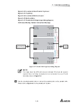
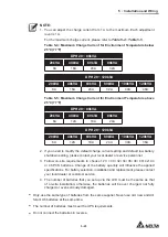
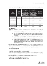
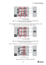
Installation and Wiring
2
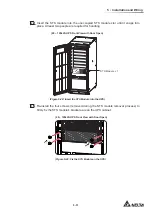
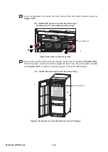
Remove the four screws from the STS module shown in
Figure 5-32
.
(20 ~ 120kVA UPS Front View with Door Open)
(Figure 5-32: Remove the Four Screws)
3
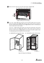
(1) For 20 ~ 80kVA UPS’s STS module, pull out the STS module from the slot (two
people are required) (see
Figure 5-33
). When the STS module cannot be pulled out
any more, please lift the STS module up (see
Figure 5-34
) in order to continuously pull
out the module from the UPS cabinet.
(2) For 20 ~ 120kVA UPS’s STS module, pull out the STS module from the slot (two
people are required) (see
Figure 5-33
). When the STS module cannot be pulled out
any more, press the lock (see
Figure 5-35
) on the left side of the STS module in order
to continuously pull out the module from the UPS cabinet.
D
IS
P
L
A
Y
/C
O
N
S
O
L
E
E
M
S
RESE
T
GND
B A
GND
B A
MOD
BUS
BMS
S3
S4
BT3 BT4
USB
RS-232
P4
P5
P6
P2
BATT.
START
BATT.
START
P3
P4
PARALLEL
PARALLEL
(20 ~ 120kVA UPS Front View with Door Open)
(20 ~ 80kVA UPS Front View with Door Open)
INPUT
BREAKER
OUTPUT
BREAKER
BYPASS
BREAKER
MANUAL BYPASS
BREAKER
INPUT
BRE
AKER
OUTPUT
BREAK
ER
BYPA
SS
BREAKER
MANUAL
BYP
ASS
BREAKER
STS Module
1
STS Module
1
(Figure 5-33: Remove the STS Module)
Summary of Contents for Modulon DPH series
Page 26: ......
Page 58: ......
Page 168: ......
Page 237: ...8 1 8 Optional Accessories 8 Optional Accessories...
Page 240: ......
Page 241: ...9 1 9 Maintenance Maintenance 9...
Page 243: ...A1 1 Appendix 1 7HFKQLFDO 6SHFL FDWLRQV Technical 6SHFL FDWLRQV A1 A1...
Page 246: ......
Page 247: ...A2 1 Appendix 2 Warranty Warranty A2 A2...
Page 250: ......

