background image

5 - 2 9

5

Installation and Wiring 

No.

External Battery Cabinet Status

Alarm

6

Battery Disconnected (Missing)

Sounds once every second.

7

Battery Over Charged

Long beep.

8

Battery Test Fail

Sounds for 50ms every second.

9

Battery End of Discharge Imminent

Sounds for 50ms every second.

10

Battery End of Discharge

Long beep.

11

Battery Life Time Expired

Sounds for 50ms every 3 seconds

.

5.7 STS 

Module

NOTE:

1.  The UPS has two different system cabinets, 20 ~ 80kVA and 20 ~ 120 kVA. 

Their exterior and size are the same (see 

Figure 2-1

 and 

Figure 2-2

), but 

their power module slot’s quantity, location, STS module’s size and weight are 

GLႇHUHQWVHH

2.6 Internal View

 and 

Figure 2-4

).

2.  For these two system cabinets, their power modules and STS modules’ 

installation and removal methods are the same; thus, the diagram of 20 ~ 120 
kVA cabinet is mostly taken as an example in chapters 

5.7 STS Module

,

5.7.1

STS Module Installation

, and 

5.7.2 STS Module Removal

.

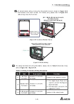
The hot swappable STS module has been installed inside the UPS in the Delta factory 
before shipment. Please see 

Figure 5-25

 for its location.

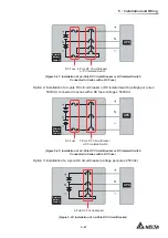
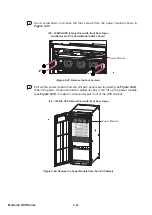
DISPLAY

REPO

NC

NO

EXT. BATT

TEMP.

BT1 BT2

EXT.SWIT

CH

STATUS

S1

S2

S3

S4

BT3 BT4

O/P DRY

CONTACT

USB

RS-232

P1

P2

P3

P4

P5

P6

I/P DRY

CONTACT

P1

P2

BATT.

START

BATT.

START

P3

P4

PARALLEL

PARALLEL

D

IS

P

L

A

Y

/C

O

N

S

O

L

E

E

M

S

RESET

GND  B

A GND

B A

MODBU

S BMS

INPUT

BREAKER

OUTPUT

BREAKER

BYPASS

BREAKER

MANUAL

 BYPASS

BREAKER

(20 ~ 120kVA UPS Front View with Door Open)

STS Module 

˜

1

(Figure 5-25: STS Module Location)

Summary of Contents for Modulon DPH series

Page 1: ...Delta UPS Modulon Family The power behind competitiveness www deltapowersolutions com DPH Series Three Phase 20 80 kVA 20 120 kVA User Manual...

Page 2: ...this product Any disposition duplication dissemination reproduction modification translation extraction or usage of this Manual in whole or in part is prohibited without the prior written permission...

Page 3: ...ode_ Single Input_ Single Unit 3 4 3 1 4 Manual Bypass Mode_ Single Input_ Single Unit 3 4 3 1 5 ECO Mode_ Single Input_ Single Unit 3 6 3 1 6 Frequency Conversion Mode_ Single Input_ Single Unit 3 6...

Page 4: ...t s 3 30 4 Communication Interfaces 4 1 4 1 Communication Interfaces on the Front of the UPS with Front Door Open 4 2 4 1 1 Display Port 4 4 4 1 2 REPO Dry Contacts 4 4 4 1 3 External Battery Temperat...

Page 5: ...2 3 Bypass Mode Start up Procedures 6 10 6 2 4 Manual Bypass Mode Start up Procedures 6 13 6 2 5 ECO Mode Start up Procedures 6 18 6 2 6 Frequency Conversion Mode Start up Procedures 6 22 6 2 7 Green...

Page 6: ...s 7 42 7 10 1 Bypass Setting 7 42 7 10 2 Mode Setting 7 43 7 10 3 Output Setting 7 44 7 10 4 Battery Charging Setting 7 45 7 10 5 Parallel Setting 7 48 7 10 6 Dry Contact Setting 7 49 7 10 7 General S...

Page 7: ...1 1 1 Important Safety Instructions 1 Important Safety Instructions 1 1 Installation Warnings 1 2 Connection Warnings 1 3 Usage Warnings 1 4 Storage Warnings 1 5 Standard Compliance...

Page 8: ...to the UPS make sure the UPS is grounded to avoid a possible risk of current leakage y You can parallel at maximum eight UPS units y The UPS must be connected with an external battery cabinet user sup...

Page 9: ...the system s overload capacity please refer to Appendix 1 Technical Specifications into consideration Besides the short circuit capacity of the upstream protective devices must be equal to or larger...

Page 10: ...perature 20 C 25 C 68 F 77 F for at least one hour to avoid moisture con densing inside the UPS y Do not put beverages on the UPS external battery cabinet s or any other accessory associated with the...

Page 11: ...ing source prior to connecting or disconnecting the batteries terminals y You must contact Delta customer service if either of the following events occurs 1 Liquid is poured or splashed on the UPS 2 T...

Page 12: ...6 Modulon DPH Series 1 5 Standard Compliance y EN 62040 1 y EN 61000 6 4 y EN 62040 2 Category C3 y EN 61000 4 2 y EN 61000 4 3 y EN 61000 4 4 y EN 61000 4 5 y EN 61000 4 6 y EN 61000 4 8 y EN 61000 2...

Page 13: ...Introduction 2 Introduction 2 1 General Overview 2 2 Package Inspection 2 3 Functions Features 2 4 Exterior and Dimensions 2 5 Front View 2 6 Internal View 2 7 Rear View 2 8 Tri color LED Indicator B...

Page 14: ...effective solution to your power requirements and produces greater electric power H FLHQF DW OHVV FRVW 7KH XQLW SURYLGHV GLYHUVL HG FRPPXQLFDWLRQ LQWHUIDFHV DQG FRPPXQLFDWLRQ SURWRFROV 6103 and MODBUS...

Page 15: ...tery temperature dry contacts and 2 external switch breaker status dry contacts please refer to Figure 4 3 2 PCS 12 10 Pin Dry Contact Terminal Block used for input and output dry contacts please refe...

Page 16: ...quency 3Hz the UPS will transfer to bypass mode other ZLVH WKH 836 ZLOO WUDQVIHU WR QRUPDO PRGH WR UHDFK KLJKHU H FLHQF y Both auxiliary power and control circuit adopt redundancy design which doubly...

Page 17: ...t log download of the UPS For relevant location and information please refer to Figure 4 25 y Built in USB ports located at the rear of the touch panel allow upgrade of the UPS touch panel power modul...

Page 18: ...ns 2 5 Front View On the front of the UPS there are a 10 color touch panel a tri color LED indicator a door switch four casters and four leveling feet Please see Figure 2 2 10 Color Touch Panel Door S...

Page 19: ...o open the UPS front door 90 90 Pull Up Pull Up Figure 2 3 How to Open the UPS Front Door 2 6 Internal View WARNING Only authorized Delta engineers or service personnel can perform installation wiring...

Page 20: ...TT START P3 P4 PARALLEL INPUT BREAKER OUTPUT BREAKER BYPASS BREAKER MANUAL BYPASS BREAKER DISPLAY EMS CONSOLE RESET GND B A GND B A MODBUS BMS DISPLAY EMS CONSOLE RESET GND B A GND B A MODBUS BMS INPU...

Page 21: ...5 7 STS Module NOTE For 20 80kVA UPS its STS module s size and weight are smaller and lighter than that of 20 120kVA UPS 4 The UPS has four breakers which are Input Breaker Q1 Bypass Breaker Q2 Manual...

Page 22: ...UAL BYPASS BREAKER Internal View with Front Door Open Wiring Terminal Cover Removal Battery Input Figure 2 8 Wiring Terminals_ Battery Input AC INPUT L1 L2 L3 L1 L2 L3 L1 L2 L3 BYPASS INPUT UPS OUTPUT...

Page 23: ...l cover removal maintenance and operation If you want to execute any action mentioned above by yourself the action must be under the supervision of authorized Delta engineers or service personnel The...

Page 24: ...Power Flow UPS 1 1 SETUP MAINTENANCE 2 WARNING LOG IN Administrator Power Flow Summary EMS System Status 10 15 May 25 2018 Tri color LED Indicator Figure 2 12 Tri color LED Indicator Location 2SHQ WK...

Page 25: ...reen Yellow ON y Indicates the UPS s current operation mode for its corresponding text shown in the upper right corner of the LCD screen please refer to the following table UPS Operation Mode Text on...

Page 26: ......

Page 27: ...n Modes 3 Operation Modes 3 1 Single Input 3 2 Dual Input 3 3 Hot Standby Redundancy Only For Dual Input At Least Two UPSs 3 4 Common Battery Only for Parallel UPSs connecting to the Same External Bat...

Page 28: ...pansion Only UPSs with the same capacity voltage frequency and version can be paralleled For version information please refer to 7 11 7 Version S N Please only use the provided parallel cable to paral...

Page 29: ...curs In Battery mode the batteries provide DC power and the UPS converts it into AC power and supplies it to the connected critical loads via the Output Breaker Q4 During the conversion process output...

Page 30: ...ch Q5 Figure 3 3 Bypass Mode Diagram_ Single Input Single Unit 3 1 4 Manual Bypass Mode_ Single Input_ Single Unit WARNING 1 In Manual Bypass mode make sure that all of the breakers except the Manual...

Page 31: ...OHDVH VHOHFW YES 3 Turn ON the Manual Bypass Breaker Q3 4 Turn OFF the Bypass Breaker Q2 5 Turn OFF the Input Breaker Q1 and Output Breaker Q4 6 Turn OFF each external battery cabinet s breaker Q5 Q 0...

Page 32: ...Input_ Single Unit NOTE 1 Frequency Conversion mode is only applicable to single UPS but not to parallel UPSs 2 When the UPS runs in Frequency Conversion mode once the inverter becomes R WKHUH LV QR E...

Page 33: ...me as On Line mode but the difference is that the system will DXWRPDWLFDOO GHWHFW WKH RXWSXW VWDWXV L H WRWDO ORDG FDSDFLW WR GHFLGH ZKLFK VSHFL F SRZHU PRGXOHV VKRXOG EH IXOO SRZHUHG RQ RU LGOH LQ RU...

Page 34: ...oad condition Before you activate Energy Recycle mode please make sure that the Manual Bypass Breaker Q3 Output Breaker Q4 and each external battery cabinet s battery breaker Q5 are in the OFF status...

Page 35: ...s load is larger than the total capacity of the UHPDLQLQJ SDUDOOHO XQLWV DOO 836V LQYHUWHUV ZLOO WXUQ R DQG WKH WRWDO ORDGV ZLOO EH VXSSOLHG by bypass power During On Line mode parallel each UPS s tr...

Page 36: ...output voltage remains the same and during Battery mode parallel each UPS s tri color LED illuminates yellow and each UPS s LCD shows the text Battery in the upper right corner Please refer to Figure...

Page 37: ...ruption The critical loads will be equally shared by all parallel units After the abnormalities mentioned above are eliminated the parallel UPSs will switch back to On Line mode from Bypass mode Durin...

Page 38: ...l UPSs if you want to turn off one of the parallel UPSs for maintenance please make sure the total connected critical loads will not exceed the remaining parallel units total capacity In Manual Bypass...

Page 39: ...ion Modes MAIN LOAD MAIN 1 2 Q1 Q2 Q4 Q3 Batteries Rectifier Inverter Static Switch Q1 Q2 Q4 Q3 Batteries Rectifier Inverter Static Switch Q5 Q5 Figure 3 12 Manual Bypass Mode Diagram_ Single Input Pa...

Page 40: ...uency 3Hz each parallel UPS works in Bypass mode otherwise each parallel UPS runs in On Line mode During ECO mode parallel each UPS s tri color LED illuminates green and each UPS s LCD shows the text...

Page 41: ...l load FDSDFLW WR GHFLGH ZKLFK VSHFL F SRZHU PRGXOHV VKRXOG EH IXOO SRZHUHG RQ RU LGOH LQ RUGHU WR DFKLHYH KLJKHU H FLHQF RI WKH 836 XULQJ UHHQ PRGH SDUDOOHO HDFK 836 V WUL color LED illuminates green...

Page 42: ...and the text On Line appears in the upper right corner of the screen MAIN LOAD BYPA Q1 Q2 Q4 Q3 Batteries Rectifier Inverter Static Switch Q5 Figure 3 15 On Line Mode Diagram_ Dual Input Single Unit 3...

Page 43: ...f down If the UPS detects the bypass AC source is normal it will automatically switch to Bypass mode to protect the connected critical loads from power interruption Please refer to Figure 3 17 After t...

Page 44: ...ypass Breaker Q3 as they may carry high voltage XULQJ 0DQXDO SDVV PRGH WKH 836 V LQSXW SRZHU LV FRPSOHWHO FXW R DQG the connected critical loads are not protected When the UPS needs maintenance you ca...

Page 45: ...Setting In ECO mode when the bypass AC source s input voltage and frequency are within the setup range default voltage 10 and frequency 3Hz the UPS works in Bypass mode otherwise the UPS runs in On L...

Page 46: ...UPS is manually set in Frequency Conversion mode the inverter will automatically VHOHFW RU DV WKH HG RXWSXW IUHTXHQF IWHU WKH RXWSXW IUHTXHQF LV GHWHUPLQHG the system will automatically disable the by...

Page 47: ...OO GHWHFW WKH RXWSXW VWDWXV L H WRWDO ORDG FDSDFLW WR GHFLGH ZKLFK VSHFL F SRZHU PRGXOHV VKRXOG EH IXOO SRZHUHG RQ RU LGOH LQ RUGHU WR DFKLHYH KLJKHU H FLHQF RI the UPS For the Green mode diagram plea...

Page 48: ...load is larger than the total capacity of the UHPDLQLQJ SDUDOOHO XQLWV DOO 836V LQYHUWHUV ZLOO WXUQ R DQG WKH WRWDO ORDGV ZLOO EH VXSSOLHG by bypass power During On Line mode parallel each UPS s tri c...

Page 49: ...ut voltage remains the same During Battery mode parallel each UPS s tri color LED illuminates yellow and each UPS s LCD shows the text Battery in the upper right corner Please refer to Figure 3 23 for...

Page 50: ...ption The critical loads will be equally shared by all parallel units After the abnormalities mentioned above are eliminated the parallel UPSs will switch back to On Line mode from Bypass mode During...

Page 51: ...HO 836V LI RX ZDQW WR WXUQ R RQH RI WKH SDUDOOHO 836V IRU PDLQWHQ ance please make sure the total connected critical loads will not exceed the remaining parallel units total capacity In Manual Bypass...

Page 52: ...Series MAIN LOAD MAIN 1 2 BYPA BYPA Q1 Q2 Q4 Q3 Batteries Rectifier Inverter Static Switch Q1 Q2 Q4 Q3 Batteries Rectifier Inverter Static Switch Q5 Q5 Figure 3 25 Manual Bypass Mode Diagram_ Dual Inp...

Page 53: ...3Hz each parallel UPS works in Bypass mode otherwise each parallel UPS runs in On Line mode During ECO mode parallel each UPS s tri color LED illuminates green and each UPS s LCD shows the text ECO i...

Page 54: ...d FDSDFLW WR GHFLGH ZKLFK VSHFL F SRZHU PRGXOHV VKRXOG EH IXOO SRZHUHG RQ RU LGOH LQ RUGHU WR DFKLHYH KLJKHU H FLHQF RI WKH 836 XULQJ UHHQ PRGH SDUDOOHO HDFK 836 V WUL color LED illuminates green and...

Page 55: ...personnel In normal condition it is the UPS 2 inverter that supplies power to the critical loads Both UPS 1 UPS 2 tri color LEDs illuminate green When the UPS 2 inverter becomes abnormal the UPS 2 wi...

Page 56: ...arge Voltage 1 Charge Current Max etc For more information please refer to 7 10 4 Battery Charging Setting NOTE 1 For common battery application please use the LCD to set each UPS s float charge volta...

Page 57: ...MAIN 1 2 BYPA BYPA Q1 Q2 Q4 Q3 Q5 Rectifier Inverter Static Switch Q1 Q2 Q4 Q3 Q5 Batteries Rectifier Inverter Static Switch Figure 3 29 Common Battery Diagram_ only for Parallel UPSs Connecting to th...

Page 58: ......

Page 59: ...4 1 4 Communication Interfaces 4 Communication Interfaces 4 1 Communication Interfaces on the Front of the UPS with Front Door Open 4 2 Communication Interfaces at the Rear of the Touch Panel...

Page 60: ...SOLE RESET GND B A GND B A MODBUS BMS 20 120kVA UPS Internal View with Front Door Open 4 1 Communication Interfaces on the Front of the UPS with Front Door Open 4 2 Communication Interfaces at the Rea...

Page 61: ...s and information of the Delta lithium ion batteries For relevant information please refer to 7 9 6 Battery Status 7 10 4 Battery Charging Setting and 7 10 7 General Setting If you have any questions...

Page 62: ...e REPO dry contacts provide normally open NO and normally closed NC these two options for use REPO NC NO UPS 5V 1 2 3 4 Buffer Buffer NO NC 5V Figure 4 4 REPO Dry Contacts Design NOTE If you want to e...

Page 63: ...e Dry Contacts You can use the external battery temperature dry contacts BT1 BT2 BT3 and BT4 to detect at maximum four external battery cabinets temperature You need to purchase the battery cabinet te...

Page 64: ...al output switch or breaker detection Detect the external output switch or breaker s status default S3 4 External manual bypass switch or breaker detection Detect the external manual bypass switch or...

Page 65: ...O DRY E_NO DRY D_NO DRY C_NO DRY B_NO DRY A_NO COMM_F COMM_E COMM_D COMM_C COMM_B COMM_A 10 112 6 8 2 4 9 11 5 7 1 3 12VS DRY 6 12VS DRY 5 12VS DRY 4 12VS DRY 3 12VS DRY 2 12VS DRY 1 P6 Max 0 5A 12V P...

Page 66: ...ical loads 11 EPO Activated 7KH 32 EXWWRQ LV SUHVVHG WR XUJHQWO SRZHU R WKH UPS 12 Load On Manual Bypass The Manual Bypass Breaker Q3 is turned on and the UPS transfers to manual bypass mode 13 Batter...

Page 67: ...12 RU QRUPDOO FORVHG 1 DFK LQSXW GU FRQWDFW FDQ EH DVVLJQHG ZLWK D VSHFL F HYHQW There are ten events that can be assigned according to your applications For information about the ten events please re...

Page 68: ...batteries you must set up KDUJHU 2 3RVLWLYH and Charger Off Negative these two items Please refer to 7 10 4 Battery Charging Setting and 7 10 6 Dry Contact Setting to perform relevant setup If you hav...

Page 69: ...mmunication Card s LED Indicator Master Parallel Communication Card Backup Parallel Communication Card s LED Indicator Backup Parallel Communication Card Figure 4 13 Location of Master and Backup Para...

Page 70: ...t shown in Figure 4 15 to monitor the status and information of the Delta lithium ion batteries For relevant information please refer to 7 9 6 Battery Status 7 10 4 Battery Charging Setting and 7 10 7...

Page 71: ...ime to avoid power interruption DISPLAY REPO NC NO EXT BATT TEMP BT1 BT2 EXT SWITCH STATUS S1 S2 S3 S4 BT3 BT4 O P DRY CONTACT USB RS 232 P1 P2 P3 P4 P5 P6 I P DRY CONTACT P1 P2 BATT START BATT START...

Page 72: ...you perform the following wiring actions 5 The UPS has two different system cabinets 20 80kVA and 20 120 kVA Their top entry and bottom entry methods are the same thus in this chapter only the diagra...

Page 73: ...4 22 INPUT BREAKE R OUTPUT BREAKE R BYPASS BREAKE R MANUAL BYPASS BREAKE R 20 120kVA UPS Internal View with Front Door Open Remove Two Wiring Panels Each Has Four Screws Remove Every Power Module Slot...

Page 74: ...oor Open Wiring Terminal Cover Removal Bottom Cover 3 Each Cover Has Two Screws Figure 4 23 Bottom Covers Location 4 Follow Figure 4 24 1 3 to perform bottom entry 20 120kVA UPS Internal View with Fro...

Page 75: ...n example 2 It is suggested that you adopt top entry for the communication interfaces located at the rear of the touch panel For relevant routing and top entry information please refer to 4 1 13 Routi...

Page 76: ...to 8 Optional Accessories 4 DISPLAY Before shipment the DISPLAY port has been connected to the other display port shown in Figure 4 3 with the designated cable in Delta factory 5 EMS CONSOLE Connects...

Page 77: ...Installation and Wiring 5 1 Before Installation and Wiring 5 2 Installation Environment 5 3 UPS Transportation 5 4 Fixing the UPS 5 5 Wiring 5 6 External Battery Cabinet Connection Warnings 5 7 STS M...

Page 78: ...et Connection Warnings for relevant information y In this user manual the meaning of Q1 Q2 Q3 Q4 and Q5 represents the following Code Meaning Q1 Input Breaker Q2 Bypass Breaker Q3 Manual Bypass Breake...

Page 79: ...2 2 lb ft2 388 2 kg m2 79 4 lb ft2 423 5 kg m2 86 6 lb ft2 458 8 kg m2 93 8 lb ft2 494 1 kg m2 101 0 lb ft2 529 4 kg m2 108 3 lb ft2 y The UPS is of top or bottom wiring Please leave adequate space fo...

Page 80: ...RQPHQW ZKHUH UHSURRI PDWHULDOV DUH XVHG WR FRQVWUXFW WKH ZDOOV RRUV DQG FHLOLQJV QVWDOO WKH 836 RQ D RRU WKDW LV PDGH RI QRQFRPEXVWLEOH PDWHULDOV y R QRW DOORZ XQDXWKRUL HG SHUVRQQHO WR HQWHU WKH LQVW...

Page 81: ...casters to move the unit over a long distance 5 4 Fixing the UPS NOTE When handling or moving the UPS please use appropriate equipment e g forklift Please follow the steps below 1 HIRUH LQJ WKH 836 L...

Page 82: ...w Nut 3 Figure 5 3 Balance Support Installation_ Front of the UPS Rear View Expansion Screw Nut 3 M10 Screw 3 1 2 Floor Balance Support Figure 5 4 Balance Support Installation_ Rear of the UPS NOTE Pl...

Page 83: ...yourself the action must be under the supervision of authorized Delta engineers or service personnel y Before wiring or making any electrical connection make sure that the power supplied to WKH LQSXW...

Page 84: ...nt at output voltage 220V 30A 61A 91A 121A 152A 182A Recommended cable size L1 L2 L3 N 4 mm2 1 PC 10 AWG x 1 PC 10 mm2 1 PC 6 AWG x 1 PC 25 mm2 1 PC 2 AWG x 1 PC 35 mm2 1 PC 1 AWG x 1 PC 50 mm2 1 PC 1...

Page 85: ...WKH JURXQG and you require that the VNG of the UPS should be zero we suggest that you install an isola tion transformer in front of the input side of the UPS and connect the isolation transformer s s...

Page 86: ...rds and components might be damaged after the UPS is powered on 6LQJOH QSXW XDO QSXW 0RGL FDWLRQ WARNING Only authorized Delta engineers or service personnel can modify the single input dual input set...

Page 87: ...s shown in Figure 5 7 AC INPUT L1 L2 L3 L1 L2 L3 L1 L2 L3 BYPASS INPUT UPS OUTPUT AC INPUT L1 L2 L3 L1 L2 L3 L1 L2 L3 BYPASS INPUT UPS OUTPUT INPUT BREAKER OUTPUT BREAKER BYPASS BREAKER MANUAL BYPASS...

Page 88: ...oltage is 240Vdc y Single Input Single Unit When there is only one AC power source single unit wiring procedures are as follows NOTE The UPS adopts top or bottom wiring Please leave adequate space on...

Page 89: ...BYPASS BREAKER Internal View with Front Door Open Wiring Terminal Cover Removal L1 L2 L3 UPS Output Figure 5 10 Wiring Terminals_ UPS Output AC INPUT L1 L2 L3 L1 L2 L3 L1 L2 L3 BYPASS INPUT UPS OUTPU...

Page 90: ...5 14 Modulon DPH Series Rear Top Cover Screw 2 Rear Panel Screw 6 Figure 5 12 Location of Rear Panel Top Cover Rear View with Rear Panel Removal Top Entry Figure 5 13 Top Entry...

Page 91: ...Open Wiring Terminal Cover Removal Bottom Entry Figure 5 15 Bottom Entry 4 For wiring terminals and wiring information please refer to Table 5 3 and also cross refer to Figure 5 8 Figure 5 19 Table 5...

Page 92: ...of the main AC source output and external battery cabinet s to the UPS There are two types of wiring top wiring and bottom wiring Please refer to the following to perform wiring Table 5 3 Wiring Termi...

Page 93: ...0RGL FDWLRQ to modify the UPS from single input into dual input 2 Follow the procedures 1 7 stated in the section of Single Input Single Unit 3 Connect the cables of the main AC source bypass source o...

Page 94: ...to parallel the UPS units Otherwise parallel functions will fail 3 When the UPSs are paralleled the length of each unit s bypass input cables plus output cables must be the same This ensures that the...

Page 95: ...isy Chain Method UPS Output Terminals UPS Output Terminals Parallel Port Parallel Port Parallel Port Parallel Port Parallel Port Parallel Port 3 4W 3 4W Parallel Cable Parallel Cable Parallel Cable Pa...

Page 96: ...el Setting y Dual Input Parallel Units When there are two AC power sources parallel units wiring procedures are as follows 1 Follow 6LQJOH QSXW XDO QSXW 0RGL FDWLRQ to modify the UPS from single input...

Page 97: ...hod Figure 5 19 Parallel Units Dual Input Wiring Diagram NOTE For dual input the UPS will not work normally if the main AC power s QHXWUDO 1 DQG WKH E SDVV SRZHU V QHXWUDO 1 DUH QRW UPO FRQQHFWHG RU n...

Page 98: ...UH UVW XVH RI WKH 836 7KH FKDUJLQJ SURFHGXUHV DUH DV IROORZV 1 Connect the main AC source and the external battery cabinet s to the UPS Please see 5 Installation and Wiring 2 Follow 6 UPS Operation to...

Page 99: ...o modify the default charge current setting and default low battery shutdown setting please contact your local dealer or service personnel 3 Follow on site requirements to choose 12V 30 32 34 36 38 40...

Page 100: ...leak can short circuit the batteries and lead to serious accidents For safety s sake you must insulate the batteries from their touched metal cabinets by installing insulated devices e g insulated tr...

Page 101: ...personnel 3 If you need to parallel multiple units of external battery cabinets please contact Delta service personnel for relevant information 4 To extend backup time you can parallel up to eight un...

Page 102: ...choosing the protective device please follow the instruc tions below 1 The protective device s rated current must comply with the current values shown in Table 5 6 7KH VSHFL FDWLRQV RI WKH SURWHFWLYH...

Page 103: ...HDNHU RU LVRODWHG VZLWFK YROWDJH SHU SROH 9GF FRQQHFWHG LQ VHULHV ZLWK D IXVH YROWDJH 9GF N UPS External Battery Cabinet 3 Pole DC Circuit Breaker or DC Isolated Switch DC Fuse N Figure 5 22 Installat...

Page 104: ...wer from the UPS 2 A battery can present a risk of electric shock and high short circuit current Servicing of batteries and battery cabinets must be performed or supervised E TXDOL HG VHUYLFH SHUVRQQH...

Page 105: ...nal View and Figure 2 4 2 For these two system cabinets their power modules and STS modules installation and removal methods are the same thus the diagram of 20 120 kVA cabinet is mostly taken as an e...

Page 106: ...been installed inside the UPS in the Delta factory before shipment If the STS module is removed for some reasons and you want to re install it please follow the steps below NOTE 1 Only qualified servi...

Page 107: ...NSOLE EMS RESET GND B A GND B A MODBUS BMS S3 S4 BT3 BT4 USB RS 232 P4 P5 P6 P2 BATT START BATT START P3 P4 PARALLEL PARALLEL 20 120kVA UPS Front View with Door Open STS Module 1 Figure 5 28 Insert th...

Page 108: ...Q SHUIRUP WKH IROORZLQJ 676 PRGXOH UHPRYDO procedures 2 The STS module is heavy refer to the table below At least two people are required for handling Rating Weight of STS Module 20 80kVA UPS 11 kg 24...

Page 109: ...e pull out the STS module from the slot two people are required see Figure 5 33 When the STS module cannot be pulled out any more press the lock see Figure 5 35 on the left side of the STS module in o...

Page 110: ...Lift up the STS Module Press the Lock 20 120kVA UPS s STS Module Figure 5 35 Press the Lock of the 20 120kVA UPS s STS Module 5 7 3 STS Module s LED Indicator Size W D H 444 5 575 6 86 mm 17 5 22 7 3...

Page 111: ...and size are the same see Figure 2 1 and Figure 2 2 but their power module slot s quantity location STS module s size and weight are GL HUHQW VHH 2 6 Internal View and Figure 2 4 2 For these two syste...

Page 112: ...GLQJ WR WKH LQVWUXFWLRQV stated in 5 4 Fixing the UPS continue with the following steps to install the power module optional into the UPS WARNING 1 Only qualified service personnel can perform the fol...

Page 113: ...BT4 O P DRY CONTACT USB RS 232 P1 P2 P3 P4 P5 P6 I P DRY CONTACT P1 P2 BATT START BATT START P3 P4 PARALLEL DISPLAY REPO NC NO EXT BATT TEMP BT1 BT2 EXT SWITCH STATUS S1 S2 S3 S4 BT3 BT4 O P DRY CONTA...

Page 114: ...S Internal View with front Door Open and Removal of the Power Module Slot s Cover INPUT BREAKER OUTPUT BREAKER BYPASS BREAKER MANUAL BYPASS BREAKER Figure 5 41 Insert the Power Module into the UPS 6 8...

Page 115: ...module s can support the connected critical loads 2 Only qualified service personnel can perform the following power module removal procedures 3 The power module is heavy 18 kg At least two people ar...

Page 116: ...ired see Figure 5 46 When the power module cannot be pulled out any more lift up the power module see Figure 5 47 in order to continuously pull it out of the UPS cabinet INPUT BREAKER OUTPUT BREAKER B...

Page 117: ...P4 PARALLEL PARALLEL 20 120kVA UPS Internal View with front Door Open Lift up the Power Module Figure 5 47 Lift up the Power Module 5 8 3 Power Module s LED Indicator The power module s LED indicator...

Page 118: ...ocess Flashing green _ on for 0 3 VHFRQG DQG R IRU VHFRQGV The power module is abnormal NOTE In online mode if you turn the power module s switch to the lower position the power module will shut down...

Page 119: ...6 1 6 UPS Operation 6 UPS Operation 6 1 Pre Start up Pre Turn R DUQLQJV IRU 6LQJOH 8QLW and Parallel Units 6 2 Start up Procedures 7XUQ R 3URFHGXUHV...

Page 120: ...efer to 7 10 6 Dry Contact Setting 3 Before operation ensure that installation and wiring have been completely done according to 5 Installation and Wiring and relevant instructions have been followed...

Page 121: ...ifference between the Neutral N and Ground is 3V 5 Check if the wiring is correct Ensure that the AC power s voltage frequency phase sequence and battery type meet the UPS s requirements 6 Check if al...

Page 122: ...following status will occur simultaneously 1 The system and each power module will start initialization After each power PRGXOH QLVKHV LQLWLDOL DWLRQ HDFK SRZHU PRGXOH V IDQV ZLOO VWDUW UXQQLQJ HDFK...

Page 123: ...cabinets 20 80kVA and 20 120 kVA Their communication interfaces and locations are the same thus in this chapter only the diagram of 20 120 kVA UPS is taken as an example DPH 20 120kVA UPS Internal Vi...

Page 124: ...the tri color LED indicator will illuminate yellow For the location of the tri color LED indicator please refer to Figure 2 12 Bypass POWER FLOW Maintenance Bypass Bypass Mains 90 5 mins Load 30 MEASU...

Page 125: ...re 6 5 On Line Mode Screen 6 2 2 Battery Mode Start up Procedures WARNING 1 For parallel units please follow 6 2 3 Bypass Mode Start up Procedures to turn on each parallel UPS After confirming that pa...

Page 126: ...DWH UHG UVW DQG WKHQ WKH FDUG ZLOO VWDUW initialization After initialization the parallel communication card s LED indicator will illuminate yellow For more information please refer to 4 1 7 Parallel...

Page 127: ...YES Standby MEASUREMENT Power Flow UPS 1 1 SETUP MAINTENANCE EVENT LOG POWER ON No Yes LOG IN User 10 15 May 25 2018 Figure 6 8 Power on Reminder Screen 8 After selection of YES to start up the UPS s...

Page 128: ...uxiliary power card s LED indicator will illuminate green and the following status will occur simultaneously 1 The system and each power module will start initialization After each power PRGXOH QLVKHV...

Page 129: ...ps running and its LED indicator remains green After each power module finishes establishing DC BUS voltage the charger will start to charge the batteries If the bypass AC source is within the normal...

Page 130: ...25 2018 Load 0 UPS 1 1 Local UPS 1 2 Read Only UPS 1 3 Read Only UPS 1 1 Power Flow UPS 1 1 Parallel Group ID No Parallel ID No Figure 6 12 Parallel Group ID No Parallel ID No Inquiry Screen 9 For sin...

Page 131: ...e OFF position and use a voltmeter to check if there is any high voltage LQVLGH WKH 836 2QO DIWHU RX KDYH FRQ UPHG WKDW WKHUH LV QR KLJK YROWDJH LQ the UPS can service personnel perform UPS maintenanc...

Page 132: ...eminder Screen 4 If normal please select YES After that the UPS will shut down the inverter and transfer to run in Bypass mode 5 QVXUH WKDW WKH 836 UXQV LQ SDVV PRGH IWHU FRQ UPDWLRQ WXUQ ON the Manua...

Page 133: ...and Bypass Breaker Q2 each auxiliary power card s LED indicator will illuminate green and the following status will occur simultaneously 1 The system and each power module will start initialization Af...

Page 134: ...US voltage the charger will start to charge the batteries If the bypass AC source is within the normal range the UPS will transfer to run in Bypass mode the LCD screen will show as Figure 6 18 and the...

Page 135: ...and perform self inspection At the same time the system begins synchronization with the bypass AC source After the self inspection is completed the UPS will automatically transfer to run in On Line m...

Page 136: ...tus will occur simultaneously 1 The system and each power module will start initialization After each power PRGXOH QLVKHV LQLWLDOL DWLRQ HDFK SRZHU PRGXOH V IDQV ZLOO VWDUW UXQQLQJ HDFK power module w...

Page 137: ...ch power module finishes establishing DC BUS voltage the charger will start to charge the batteries If the bypass AC source is within the normal range the UPS will transfer to run in Bypass mode the L...

Page 138: ...Flow Summary EMS System Status 10 15 May 25 2018 Administrator Login ON OFF Button Figure 6 23 Main Screen_ Administrator Login ON OFF Button Location 8 Go to SETUP Mode Setting ECO Bypass UPS 1 1 MO...

Page 139: ...n with the bypass AC source After the self inspection is completed the UPS will automatically transfer to run in On Line mode After the system confirms that the bypass voltage is normal the UPS will a...

Page 140: ...ower PRGXOH QLVKHV LQLWLDOL DWLRQ HDFK SRZHU PRGXOH V IDQV ZLOO VWDUW UXQQLQJ HDFK power module will start establishing DC BUS voltage and each power module s LED indicator will illuminate green 7KH S...

Page 141: ...ch power module finishes establishing DC BUS voltage the charger will start to charge the batteries If the bypass AC source is within the normal range the UPS will transfer to run in Bypass mode the L...

Page 142: ...n ON OFF Button Figure 6 29 Main Screen_ Administrator Login ON OFF Button Location 8 Go to SETUP Mode Setting Frequency Conversion WARNING Please note that once you select Frequency Conversion mode v...

Page 143: ...erform self inspection After the self inspection is completed the UPS will automatically transfer to run in Frequency Conversion mode and the output frequency will be the same as setup value Now the t...

Page 144: ...atus will occur simultaneously 1 The system and each power module will start initialization After each power PRGXOH QLVKHV LQLWLDOL DWLRQ HDFK SRZHU PRGXOH V IDQV ZLOO VWDUW UXQQLQJ HDFK power module...

Page 145: ...ch power module finishes establishing DC BUS voltage the charger will start to charge the batteries If the bypass AC source is within the normal range the UPS will transfer to run in Bypass mode the L...

Page 146: ...n ON OFF Button Figure 6 35 Main Screen_ Administrator Login ON OFF Button Location 8 Go to SETUP Mode Setting Green Bypass UPS 1 1 MODE SETTING MEASUREMENT Mode Setting SETUP MAINTENANCE EVENT LOG LO...

Page 147: ...utomatically transfer to run in Green mode and the system will automatically detect WKH RXWSXW VWDWXV L H WRWDO ORDG FDSDFLW WR GHFLGH ZKLFK VSHFL F SRZHU PRGXOHV VKRXOG EH IXOO SRZHUHG RQ RU LGOH LQ...

Page 148: ...XQLFDWLRQ FDUG V LQGLFDWRU ZLOO LOOXPLQDWH UHG UVW DQG WKHQ the card will start initialization After initialization the parallel communication card s LED indicator will illuminate green NOTE If you pu...

Page 149: ...ins Load 0 MEASUREMENT Power Flow UPS 1 1 SETUP MAINTENANCE LOG IN User 2 WARNING Power Flow Summary EMS System Status 10 15 May 25 2018 User Login Bypass Figure 6 40 Main Screen_ User Login 6 Please...

Page 150: ...ll pop up to ask if you want to power on the UPS s inverter Please select YES Bypass MEASUREMENT Power Flow UPS 1 1 SETUP MAINTENANCE POWER ON No Yes LOG IN Administrator 2 WARNING 10 15 May 25 2018 F...

Page 151: ...ynchronized to all parallel UPSs RU SDUDOOHO DSSOLFDWLRQ LI RX MXVW ZDQW WR RSHUDWH D VSHFL F 836 EXW QRW DOO parallel ones please contact service personnel 1 In On Line mode the LCD shows the followi...

Page 152: ...n and the connected critical loads won t be protected At this moment each power module keeps charging the batteries the tri color LED indicator illuminates yellow and the following screen Figure 6 47...

Page 153: ...he tri color LED indicator illuminates yellow For the tri color LED indicator location please refer to Figure 2 12 Battery POWER FLOW Maintenance Bypass Bypass Mains 90 5 mins Load 30 MEASUREMENT Powe...

Page 154: ...the tri color LED indicator location please refer to Figure 2 12 Standby POWER FLOW Maintenance Bypass Bypass Mains 90 5 mins Load 0 MEASUREMENT Power Flow UPS 1 1 SETUP MAINTENANCE LOG IN User 2 WAR...

Page 155: ...refer to Figure 2 12 Bypass POWER FLOW Maintenance Bypass Bypass Mains 90 5 mins Load 30 MEASUREMENT Power Flow UPS 1 1 SETUP MAINTENANCE EVENT LOG LOG IN User Power Flow Summary EMS System Status 10...

Page 156: ...breakers and power are OFF 2 0RGH 7XUQ R 3URFHGXUHV WARNING 1 For parallel units ensure that every operation procedure mentioned below is synchronized to all parallel UPSs RU SDUDOOHO DSSOLFDWLRQ LI R...

Page 157: ...is a risk of output interruption and the connected critical loads won t be protected At this moment each power module keeps charging the batteries the tri color LED indicator illuminates yellow and t...

Page 158: ...TUP MAINTENANCE EVENT LOG LOG IN Administrator On Line Green ECO Energy Recycle Frequency Conversion Select to change system mode 10 15 May 25 2018 Figure 6 56 Select Online Mode 6 Switch OFF the Inpu...

Page 159: ...e refer to Figure 2 12 Frequency Conversion POWER FLOW Maintenance Bypass Bypass Mains 90 5 mins Load 30 MEASUREMENT Power Flow UPS 1 1 SETUP MAINTENANCE EVENT LOG LOG IN User Power Flow Summary EMS S...

Page 160: ...n Now each power module keeps charging the batteries the tri color LED indicator illuminates yellow and the following screen appears Figure 6 59 For the tri color LED indicator location please refer t...

Page 161: ...ass AC source supply power to the output Bypass UPS 1 1 MODE SETTING MEASUREMENT Mode Setting SETUP MAINTENANCE EVENT LOG LOG IN Administrator On Line Green ECO Energy Recycle Frequency Conversion Sel...

Page 162: ...LED indicator location please refer to Figure 2 12 Green POWER FLOW Maintenance Bypass Bypass Mains 90 5 mins Load 30 MEASUREMENT Power Flow UPS 1 1 SETUP MAINTENANCE EVENT LOG LOG IN User Power Flow...

Page 163: ...12 Bypass POWER FLOW Maintenance Bypass Bypass Mains 90 5 mins Load 30 MEASUREMENT Power Flow UPS 1 1 SETUP MAINTENANCE EVENT LOG LOG IN User Power Flow Summary EMS System Status 10 15 May 25 2018 Fig...

Page 164: ...7 1RZ HDFK SRZHU PRGXOH SHUIRUPV 86 GLVFKDUJLQJ DQG LWV LQGLFDWRU DVKHV JUHHQ IWHU GLVFKDUJLQJ HDFK SRZHU PRGXOH V LQGLFDWRU ZLOO EH R 8 About 3 minutes later the UPS will shut down and the LCD and th...

Page 165: ...will pop up to ask if you want WR SRZHU R WKH 836 V LQYHUWHU 3OHDVH VHOHFW YES MEASUREMENT Power Flow UPS 1 1 SETUP MAINTENANCE No Yes LOG IN User POWER OFF Transfer to Bypass without Protection Energ...

Page 166: ...ease log in as an Administrator For the Administrator password please contact service personnel After login ensure that you are in the Administrator login status see Figure 6 70 Bypass POWER FLOW Main...

Page 167: ...TUP MAINTENANCE EVENT LOG LOG IN Administrator On Line Green ECO Energy Recycle Frequency Conversion Select to change system mode 10 15 May 25 2018 Figure 6 71 Select Online Mode 6 Switch OFF the Inpu...

Page 168: ......

Page 169: ...lay Hierarchy 7 2 How to Turn on the LCD 7 3 ON OFF Button 7 4 Introduction of Touch Panel and Function Keys 7 5 Password Entry 7 6 Main Screen 7 7 Main Menu 7 8 Power Flow Summary System Status 7 9 C...

Page 170: ...cle Frequency Conversion Voltage V Voltage Compensation V Frequency Hz Slew Rate Hz s PM Redundancy V Async Transfer Time ms Module Sequential Start s System Sequential Start s Battery Type Battery Ra...

Page 171: ...ist 7 The information on the LCD screen presented in 7 LCD Display Settings including the UPS operation mode machine number date time total number of alarms load battery remaining time user login or a...

Page 172: ...6 I P DRY CONTACT P1 P2 BATT START BATT START P3 P4 PARALLEL DISPLAY EMS CONSOLE RESET GND B A GND B A MODBUS BMS BATT START BATT START 20 120kVA UPS Front View with Door Open Battery Start Button x 2...

Page 173: ...setting for the ON OFF Button please go to SETUP General Setting User 2Q 2 XWWRQ Access For relevant information please refer to 7 10 7 General Setting After the touch panel is turned on in accordanc...

Page 174: ...LOG POWER ON No Yes LOG IN Administrator 10 15 May 25 2018 Figure 7 6 Power On Reminder Window y 3RZHU 2 When the ON OFF Button is green it indicates that the UPS s inverter is in the ON status Tap t...

Page 175: ...Display Yes or No Symbol Display Yes or No Description 1 UPS 1 1 Back to the Main Screen The UPS 1 1 below the icon indicates the parallel group ID the former number and the parallel ID the latter num...

Page 176: ...tion please refer to 7 5 Password Entry 6 EVENT LOG 1 Event log shortcut icon EVENT LOG Tap the icon to check all the event logs 2 When the warning icon is blue it indicates that there is no warning 2...

Page 177: ...input output and battery status of the UPS For more information please refer to 7 8 Power Flow Summary System Status EMS 11 System Status Shortcut icon for system status Tap the icon to check the sta...

Page 178: ...OFF 2 Main input screen shortcut icon 16 90 5 mins 1 Battery status Green Normal Flashing Green Gray Battery Mode Flashing Red Gray Battery Not Connected 2 Battery remaining capacity 3 Battery remaini...

Page 179: ...o Icon Function 1 Goes to the top page 2 Goes to the last page 3 Moves up 4 Moves down 5 Goes to the previous page 6 Goes to the next page 7 Increases number 8 Decreases number 9 1 1 Indicates the pag...

Page 180: ...SETUP General Setting User Language The default ODQJXDJH ZLOO EH GL HUHQW DFFRUGLQJ WR GL HUHQW FRXQWULHV 7 5 Password Entry 1 Password entry is only required for login as an Administrator User login...

Page 181: ...May 25 2018 1 The screen above indicates that the UPS is in Standby PRGH 7KH LQYHUWHU LV R DQG WKH bypass input is out of the range Bypass POWER FLOW Maintenance Bypass Bypass Mains 90 5 mins Load 30...

Page 182: ...to 7 10 2 Mode Setting and 6 2 1 Online Mode Start up Procedures Green POWER FLOW Maintenance Bypass Bypass Mains 90 5 mins Load 30 MEASUREMENT Power Flow UPS 1 1 SETUP MAINTENANCE EVENT LOG LOG IN Ad...

Page 183: ...settings please refer to 7 10 2 Mode Setting and 6 2 5 ECO Mode Start up Procedures 6 Energy Recycle POWER FLOW Maintenance Bypass Bypass Mains Load 0 0 0 mins MEASUREMENT Power Flow UPS 1 1 SETUP MAI...

Page 184: ...OG IN Administrator POWER FLOW Maintenance Bypass Bypass Mains 90 5 mins Load 30 Power Flow Summary EMS System Status 10 15 May 25 2018 After the Manual Bypass Breaker Q3 is turned on the UPS will be...

Page 185: ...e UPS s readings including the following 1 Main Input 2 Bypass Input 3 Inverter Output 4 Power Module Summary 5 UPS Output 6 Battery Status 7 EMS 8 BMS For more information please refer to 7 9 Check S...

Page 186: ...4 Test 5 Clear 6 Advanced Diagnosis 7 Version S N For more information please refer to 7 11 System Maintenance NOTE L HUHQW ORJLQ V GPLQLVWUDWRU 8VHU KDYH GL HUHQW DFFHVV WR GL HUHQW VFUHHQV inspecti...

Page 187: ...heck information related to input output and battery Please refer WR WKH JXUH EHORZ 220 0 V 220 0 V 220 0 V 220 0 V 220 0 V 220 0 V 220 0 V 220 0 V 220 0 V 227 A 227 A 227 A 272 V 272 V 30 30 30 05 00...

Page 188: ...ry EMS System Status Power Flow 01 02 03 04 2 1 5 3 4 5 5 3 4 5 1 2 4 3 5 STS Module Status Power Module Status Parallel Communication Card Status System Control Card Status Auxiliary Power Card Statu...

Page 189: ...INTENANCE EVENT LOG LOG IN Administrator EMS 10 15 May 25 2018 EMS Summary System Status Power Flow Temperature Title Humidity DI1 DI2 DI4 DI3 Normal Warning Alarm Off 7 9 Check System Readings 7 9 1...

Page 190: ...INPUT Phase Voltage V Line Voltage V Current A Frequency Hz Kilowatt Hour kWH 10 15 May 25 2018 UPS 1 1 220 0 380 0 220 0 380 0 220 0 380 0 50 0 0 On Line SETUP MAINTENANCE EVENT LOG LOG IN Administr...

Page 191: ...U items only indicate today s statistics 6 Last Reset Date The last date when Clear Kilowatt Hour was executed Please refer to 7 11 5 Clear for relevant information 1 Descriptions of the kWH Statistic...

Page 192: ...2018 07 06 CONSUMPTION Day Week Month Year Since Reset 100 75 50 25 0 By Hour 2018 08 23 13 18 Search Tick Present Peak Low Sum kWH d kWH d kWH d kWH d 0 0 0 0 2018 08 16 00 00 2018 08 16 06 00 2018...

Page 193: ...e week 3 168 pieces of data 24 hours 7 days are shown in the column chart of the week y Tap the icon on either side of the column chart to view the statistics of the previous next week y Tap one of th...

Page 194: ...IN Administrator MEASUREMENT Main Input MAIN INPUT Phase Voltage V Line Voltage V Current A Frequency Hz Kilowatt Hour kWH 10 15 May 25 2018 2 WARNING UPS 1 1 220 0 380 0 220 0 380 0 220 0 380 0 50 0...

Page 195: ...iew the statistics of the previous next day 2 At the moment of viewing if it is still within the day the minimum unit the window shows the current statistics and will keep updating For example if you...

Page 196: ...NT Main Input MAIN INPUT Phase Voltage V Line Voltage V Current A Frequency Hz Kilowatt Hour kWH 10 15 May 25 2018 2 WARNING Last Reset Date 2018 07 06 CONSUMPTION Week Month Since Reset 700 600 500 4...

Page 197: ...l 2 years 2 Interval marks Last Reset Date January of every two years and so on 3 Pieces of data lasting for 10 years since Last Reset Date are shown in the column chart The system can save and show t...

Page 198: ...Input MAIN INPUT Phase Voltage V Line Voltage V Current A Frequency Hz Kilowatt Hour kWH 10 15 May 25 2018 2 WARNING UPS 1 1 220 0 380 0 220 0 380 0 220 0 380 0 50 0 0 On Line SETUP MAINTENANCE LOG I...

Page 199: ...Reset Date 2018 07 06 CONSUMPTION Day Month Year Since Reset 1 00 0 80 0 60 0 40 0 20 0 00 By Hour 2018 08 23 13 18 Search Tick Present Peak Low Sum kWH d kWH d kWH d kWH d 0 0 0 0 2018 08 23 00 00 20...

Page 200: ...DPH Series 3 Tap the download icon to start downloading and the following screen will appear Loading data Please wait 4 After the download has been completed you will see the following screen Download...

Page 201: ...18 7 9 3 Inverter Output Path MEASUREMENT QYHUWHU 2XWSXW After entering the INVERTER OUTPUT VFUHHQ VKRZQ LQ WKH JXUH EHORZ RX FDQ YLHZ each power module s Phase Voltage Line Voltage Current and Freque...

Page 202: ...220 0 220 0 220 0 5 On Off 25 0 25 0 25 0 360 0 360 0 220 0 220 0 220 0 6 On Off 25 0 25 0 25 0 360 0 360 0 220 0 220 0 220 0 On Line UPS 1 1 SETUP MAINTENANCE EVENT LOG LOG IN Administrator MEASUREM...

Page 203: ...00 00 272 0 272 0 None None 0 0 On Line UPS 1 1 SETUP MAINTENANCE EVENT LOG LOG IN Administrator MEASUREMENT Battery Status BATTERY STATUS 1 PAGE 2 PAGE Status Test Result Battery Temp 1 C Battery Tem...

Page 204: ...l Volt V Temp C Cell Volt V Temp C After entering the screen shown above you can use the three drop down lists in the upper left corner to choose the Cabinet String and Battery Module to view the corr...

Page 205: ...I3 1 2 3 4 No Item Color Status Descriptions 1 ID Green Normal Yellow Warning Red Alarm UD 2 L HUHQW UHSUHVHQWV D GL HUHQW 06 EnviroProbe device connected to the UPS NOTE The LCD will only show the EM...

Page 206: ...to Normal respectively only when the detected value has been lowered to its corresponding Recovery value 3 Humidity Green Normal Yellow Warning Red Alarm 4 DI1 Green None Information Yellow Warning Re...

Page 207: ...25 2018 2 WARNING Log Solution Touch Panel Comm Loss PFC 1 Fan Fault Please contact service personnel for more information Please contact service personnel for more information 2 After connection of...

Page 208: ...ID by the four ID DIP switches on the left of the device following 3 2 ID DIP Switch Settings of the EnviroProbe 1000 Quick Guide NOTE 1 You must set the ID on the LCD according to the ID DIP switch...

Page 209: ...8 1 4 25 1 25 6 1 11 9 8 1 2 12 1 9 8 3 12 1 9 8 4 12 1 9 8 5 12 1 9 8 6 12 1 9 8 7 12 1 9 8 8 12 1 9 8 9 12 1 9 8 10 12 1 9 8 11 12 1 9 8 12 12 1 9 8 Cell Volt V 5 P 25 12 1 9 8 26 12 1 9 8 27 12 1...

Page 210: ...assistance NOTE 1 means that the Administrator password is needed For password information please refer to 7 5 Password Entry Bypass 3 10 Hz 9 10 UPS 1 1 SETUP MAINTENANCE EVENT LOG LOG IN Administra...

Page 211: ...Energy Recycle Frequency Conversion Select to change system mode 10 15 May 25 2018 Item Description On Line Mode Set up the UPS in On Line mode In On Line mode it is the inverter to supply power to th...

Page 212: ...customer service for assistance NOTE 1 means that the Administrator password is needed For password information please refer to 7 5 Password Entry Bypass 60 1 Hz 240 V 0 0 5 Hz s 0 5T_AC 2 s 6 s UPS...

Page 213: ...erator to avoid bearing the whole loads right away 7 10 4 Battery Charging Setting Path SETUP DWWHU KDUJLQJ 6HWWLQJ In the BATTERY CHARGING SETTING screen 1 VKRZQ LQ WKH JXUH EHORZ RX FDQ VHW XS WKH I...

Page 214: ...TENANCE EVENT LOG LOG IN Administrator MEASUREMENT Battery Charging Setting BATTERY CHARGING SETTING 1 PAGE 3 PAGE 2 PAGE 4 PAGE Battery Test Fail Voltage Battery Test Duration Auto Battery Test Inter...

Page 215: ...ure 4 15 Please contact Delta customer service if you need more information Battery Rating Voltage Set up the battery rating voltage Battery Strings Set up how many battery strings that are used on si...

Page 216: ...If enabled set up the temperature High Temperature Alarm Enable or disable the high temperature alarm If enabled set up the temperature Installation Date Record the battery installation date Next Rep...

Page 217: ...Battery setup item Otherwise the function of battery abnormality detection will fail For more information about common battery please refer to 3 4 Common Battery Only for Parallel UPSs connecting to t...

Page 218: ...EVENT LOG LOG IN Administrator MEASUREMENT Dry Contact Setting DRY CONTACT SETTING INPUT OUTPUT Event Type Normally Open Normally Open Normally Open Normally Open Normally Open Normally Open None None...

Page 219: ...17 Bypass static switch fault 18 UPS over temperature 19 Battery breaker shunt trip 20 Backfeed protection 21 UPS general alarm Set up NO normally open or NC normally closed for each output dry conta...

Page 220: ...IN Administrator MEASUREMENT General Setting GENERAL SETTING DATE TIME SCREEN USER DUST FILTER Language MODBUS ID Admin Password English 10 15 May 25 2018 1 19200 Any User Baud Rate On Off Button Acce...

Page 221: ...tion I RX KDYH LQVWDOOHG DQ GXVW OWHU SOHDVH VHOHFW Enable if not please select Disable Dust Filter Installation Date 6HW XS WKH GXVW OWHU LQVWDOODWLRQ GDWH NOTE Only when you select Enable for Dust F...

Page 222: ...MFC 7 10 8 IP Setting Path SETUP 3 6HWWLQJ After entering the IP SETTING screen 1 shown in the figure below you can set up the IROORZLQJ LWHPV 7KHVH VHWWLQJV PXVW EH FDUULHG RXW E TXDOL HG VHUYLFH SHU...

Page 223: ...QJ LWHPV 7KHVH VHWWLQJV PXVW EH FDUULHG RXW E TXDOL HG VHUYLFH SHUVRQQHO 3OHDVH contact Delta customer service for assistance On Line UPS 1 1 SETUP MAINTENANCE EVENT LOG LOG IN Administrator MEASUREME...

Page 224: ...ully NOTE 1 means that the Administrator password is needed For password information please refer to 7 5 Password Entry 7 10 10 EMS Setting Path SETUP 06 6HWWLQJ After entering the EMS SETTING screen...

Page 225: ...be adjusted according to your needs the default values are VKRZQ LQ WKH JXUHV DERYH Item Sub Item Description SENSOR ID Set the ID ID 0 ID 1 ID 15 according to the ID DIP switch set on the EMS 1000 En...

Page 226: ...r Buzzer Event Type of Input Contact EMS DI1 DI4 LCD Tri color LED Indicator Buzzer Warning LCD Historical Event LCD None Green Green No Sound No No Information Green Green No Sound No Yes Warning Yel...

Page 227: ...OG IN Administrator BMS SETTING 10 15 Sep 25 2018 MEASUREMENT 4 WARNING MAINTENANCE Main BMS Setting SETUP 1 1 Internal Resistance Enable Module Module Address String ID Module Type Status Cell Voltag...

Page 228: ...utions please refer to 10 Troubleshooting 4U Log Solution 1 On Line UPS 1 1 SETUP MAINTENANCE LOG IN Administrator MEASUREMENT Warning WARNING 10 15 May 25 2018 2 WARNING 2 1 Touch Panel Comm Loss PFC...

Page 229: ...519 01 2518 01 0128 01 5005 01 480A 01 0100 01 3200 01 STS STS STS STS STS STS STS STS 2017 10 15 10 26 36 2017 10 15 09 06 59 2017 10 15 10 27 07 2017 10 15 10 26 52 2017 10 15 10 26 36 2017 10 15 09...

Page 230: ...scription In Battery Mode Means how many times that the UPS runs in battery mode Battery Mode Duration Means how long the UPS runs in battery mode In Bypass Mode Means how many times that the UPS runs...

Page 231: ...inistrator password is needed For password information please refer to 7 5 Password Entry On Line UPS 1 1 SETUP MAINTENANCE LOG IN Administrator MEASUREMENT Clear EVENT LOG CLEAR Clear Historical Even...

Page 232: ...y of them without the consent of qualified service personnel 7 11 6 Advanced Diagnosis Path MAINTENANCE GYDQFHG LDJQRVLV After entering the ADVANCED DIAGNOSIS screen 1 VKRZQ LQ WKH JXUH EHORZ RX FDQ c...

Page 233: ...m is the same for each parallel unit 2 The Administrator password is needed for the icon UPGRADE For password information please refer to 7 5 Password Entry Path MAINTENANCE 9HUVLRQ 6 1 After entering...

Page 234: ...014AR00 07 00 0H0014AR00 07 00 4A001AR00 00 00 4A001AR00 00 00 4A001AR00 00 00 INV PFC UPS 1 1 SETUP MAINTENANCE LOG IN Administrator MEASUREMENT EVENT LOG Version S N VERSION S N MAIN S N UPGRADE Cho...

Page 235: ...4 12 For relevant information please refer to 4 1 7 Parallel Communication Card System Control Card_ MCU FPGA KHFN DQG XSGDWH WKH 0 8 RU 3 UPZDUH version of the system control card Touch Panel _ MCU C...

Page 236: ...ON S N MAIN S N UPS 1 1 SETUP MAINTENANCE LOG IN Administrator MEASUREMENT EVENT LOG Version S N UPGRADE Choose File MFC Item Sub Item Description MFC Multifunctional Communication Card MCU KHFN DQG X...

Page 237: ...8 1 8 Optional Accessories 8 Optional Accessories...

Page 238: ...net Temperature Sensor Cable Detects the temperature of an external battery cabinet connected to the UPS 5 Parallel Communication Card Provides two redundant parallel ports and one LED indicator for p...

Page 239: ...Charging Setting and 7 10 7 General Setting Please contact Delta customer service if you need more information NOTE The number of the multifunctional communication card MFC that needs to be installed...

Page 240: ......

Page 241: ...9 1 9 Maintenance Maintenance 9...

Page 242: ...ium ion batteries The battery life depends on the environment temperature the usage and the charging discharging frequency High temperature environments and high charging discharging frequency will qu...

Page 243: ...A1 1 Appendix 1 7HFKQLFDO 6SHFL FDWLRQV Technical 6SHFL FDWLRQV A1 A1...

Page 244: ...ORDG QRQ OLQHDU ORDG Power Factor 1 Frequency 50 60 Hz Overload Capability PLQXWHV PLQXWH 150 1 second Display 10 Touch Panel Interface Standard External battery temperature dry contact 4 External swi...

Page 245: ...D H 600 850 1445 mm 23 62 33 46 56 89 Weight 20 80kVA UPS without power modules 150 kg 330 7 lb 20 120kVA UPS without power modules 162 kg 357 1 lb Power Module optional 18 kg 39 7 lb 20 80kVA 20kVA 2...

Page 246: ......

Page 247: ...A2 1 Appendix 2 Warranty Warranty A2 A2...

Page 248: ...force i e war fire natural disaster etc and this warranty also expressly excludes all incidental and consequential damages Maintenance service for a fee is provided for any damage out of the warranty...

Page 249: ...ll VIC 3168 Australia T 61 3 9543 3720 E ups australia deltaww com Delta Electronics Korea Inc 1511 Byucksan Digital Valley 6 cha Gasan dong Geumcheon gu Seoul Korea 153 704 T 82 2 515 5303 E ups sout...

Page 250: ......
Reviews: