5 - 1 9
5
Installation and Wiring
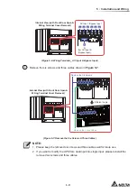
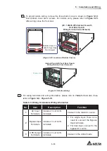
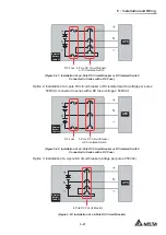
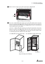
Figure 5-12: Location of Rear Panel & Top Cover
Figure 5-13: Top Entry
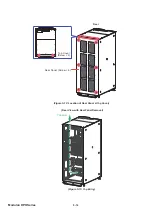
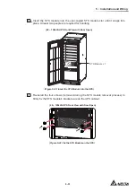
Figure 5-14: Location of Bottom Covers
Figure 5-15: Bottom Entry
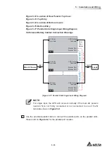
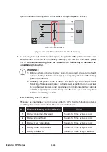
Figure 5-17: Parallel Units Single Input Wiring Diagram
5.6 External Battery Cabinet Connection Warnings
UPS 1
UPS 2
UPS 8
Loads
Main AC Source
AC Input
Terminals
AC Input
Terminals
AC Input
Terminals
UPS Output
Terminals
Daisy
Chain
Method
UPS Output
Terminals
UPS Output
Terminals
Parallel Port
Parallel Port
Parallel Port
Parallel Port
Parallel Port
Parallel Port
3Ø4W
3Ø4W
Parallel Cable
Parallel Cable
Parallel Cable
Parallel Cable
(Figure 5-17: Parallel Units Single Input Wiring Diagram)
NOTE:
For single input, the UPS will not work normally if the main AC power’s
neutral (N) is not firmly connected or not connected to one of the N
terminals shown in
Figure 5-8
.
3
Use the provided parallel cable to connect the parallel ports on the parallel units.
Please refer to
Figure 4-3
for the parallel port location.
Summary of Contents for Modulon DPH series
Page 26: ......
Page 58: ......
Page 168: ......
Page 237: ...8 1 8 Optional Accessories 8 Optional Accessories...
Page 240: ......
Page 241: ...9 1 9 Maintenance Maintenance 9...
Page 243: ...A1 1 Appendix 1 7HFKQLFDO 6SHFL FDWLRQV Technical 6SHFL FDWLRQV A1 A1...
Page 246: ......
Page 247: ...A2 1 Appendix 2 Warranty Warranty A2 A2...
Page 250: ......


