6 - 1 6
Modulon DPH Series
4
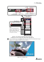
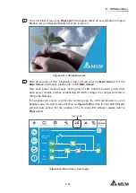
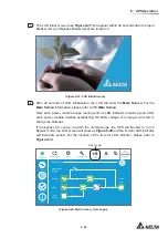
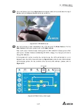
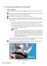
The
LCD
initial
screen
(see
Figure 6-17
) will appear within 40 seconds after the Input
Breaker (Q1) and Bypass Breaker (Q2) are turned on.
(Figure 6-17: LCD Initial Screen)
5
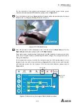
After 20 seconds of LCD initialization, the LCD will enter the
Main Screen
. For the
Main Screen
information, please refer to
7.6 Main Screen
.
Now, each power module keeps running and its LED indicator remains green. After
each power module finishes establishing DC BUS voltage, the charger will start to
charge the batteries.
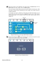
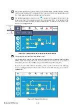
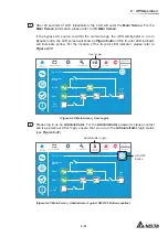
If the bypass AC source is within the normal range, the UPS will transfer to run in
Bypass mode, the LCD screen will show as
Figure 6-18
and the tri-color LED indicator
will illuminate yellow. For the location of the tri-color LED indicator, please refer to
Figure 2-12
.
Bypass
POWER FLOW
Maintenance
Bypass
Bypass
Mains
90 %
5 mins
Load
30 %
MEASUREMENT
Power Flow
UPS-1.1
SETUP
MAINTENANCE
LOG IN
User
2
WARNING
Power Flow
Summary
EMS
System Status
10:15
May 25,2018
User Login
ON/ OFF
Button
(Figure 6-18: Bypass Mode Screen_ User Login & ON/ OFF Button Location)
6
Switch
OFF
the Manual Bypass Breaker (Q3).
Summary of Contents for Modulon DPH series
Page 26: ......
Page 58: ......
Page 168: ......
Page 237: ...8 1 8 Optional Accessories 8 Optional Accessories...
Page 240: ......
Page 241: ...9 1 9 Maintenance Maintenance 9...
Page 243: ...A1 1 Appendix 1 7HFKQLFDO 6SHFL FDWLRQV Technical 6SHFL FDWLRQV A1 A1...
Page 246: ......
Page 247: ...A2 1 Appendix 2 Warranty Warranty A2 A2...
Page 250: ......

