7 - 2 1
7
LCD Display & Settings
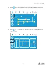
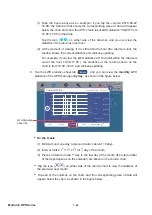
4. Tap
the
EMS
icon to check the integrated status of each optional EMS 1000 (EnviroProbe)
device connected to the UPS (Green: Normal; Yellow: Warning; Red: Alarm; Gray:
2ႇWKHLQWHJUDWHGVWDWXVLVGHWHUPLQHGE\WKHPRVWVHYHUHVWDWXVDPRQJWKHGHYLFH¶V
temperature (°C) status, humidity (%) status, and the status of input contacts DI1~DI4.
For more EMS information, please refer to
7.9.7 EMS
and
7.10.10 EMS Setting
.
0
EMS0
28.5
°C
52
%
ID
Security
Leakage
Fire
Smoke
On-Line
MEASUREMENT
EMS
UPS-1.1
SETUP
MAINTENANCE
EVENT LOG
LOG IN
Administrator
EMS
10:15
May 25,2018
EMS
Summary
System Status
Power Flow
Temperature
Title
Humidity
DI1
DI2
DI4
DI3
Normal
Warning
Alarm
Off
7.9 Check System Readings
7.9.1 Main Input
Path:
MEASUREMENT
ĺ0DLQ,QSXW
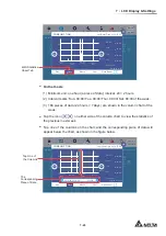
After entering the
MAIN INPUT
screen (shown in the figure below), you can view the
readings of
Phase Voltage
,
Line Voltage
,
Current
,
Frequency
and
Kilowatt-Hour
.
For more information about Kilowatt-Hour, please refer to
7.9.1.1 Check Kilowatt-Hour
.
UPS-1.1
220.0
380.0
-
220.0
380.0
-
220.0
380.0
-
50.0
0
On-Line
SETUP
MAINTENANCE
EVENT LOG
LOG IN
Administrator
MEASUREMENT
Main Input
MAIN INPUT
Phase Voltage (V)
Line Voltage (V)
Current (A)
Frequency (Hz)
Kilowatt-Hour (kWH)
10:15
May 25,2018
Summary of Contents for Modulon DPH series
Page 26: ......
Page 58: ......
Page 168: ......
Page 237: ...8 1 8 Optional Accessories 8 Optional Accessories...
Page 240: ......
Page 241: ...9 1 9 Maintenance Maintenance 9...
Page 243: ...A1 1 Appendix 1 7HFKQLFDO 6SHFL FDWLRQV Technical 6SHFL FDWLRQV A1 A1...
Page 246: ......
Page 247: ...A2 1 Appendix 2 Warranty Warranty A2 A2...
Page 250: ......


