background image

160

Adding and Replacing Parts

3

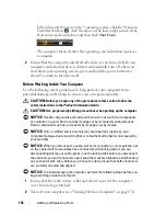
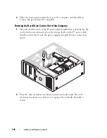
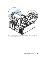
Rotate the card retention mechanism back into its original position; push 

its tip so that its tab clicks into place.

4

Reconnect both sides of the P3 power-cable bundle that is attached to the 

card retention mechanism.

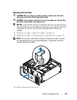
Replacing the Front Panel

1

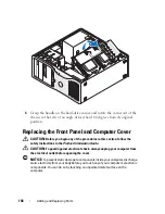
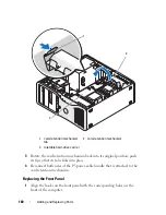
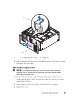
Align the hooks on the front panel with the corresponding holes on the 

front of the computer. 

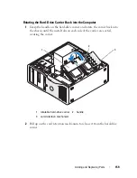
1 card-retention mechanism 

tab

2 card-retention mechanism

3 rotatable hard-drive carrier

3

1

2

Summary of Contents for Precision NX046

Page 1: ...w w w d e l l c o m s u p p o r t d e l l c o m Dell Precision T5400 User s Guide Model DCTA ...

Page 2: ...ver without the written permission of Dell Inc is strictly forbidden Trademarks used in this text Dell the DELL logo Dell Precision and Dell OpenManage are trademarks of Dell Inc Intel Speedstep and Xeon are registered trademarks of Intel Corporation Microsoft Windows and Windows Vista are either trademarks or registered trademarks of Microsoft Corporation in the United States and or other countri...

Page 3: ...ors Tower Orientation 22 Front View Desktop Orientation 24 Back View Desktop Orientation 25 Inside View 26 Inside View Hard Drive Bay Rotated Out 27 System Board Components 28 Cable Colors 29 Changing Between Tower and Desktop Modes 30 Specifications 36 3 Advanced Features 45 LegacySelect Technology Control 45 Manageability 45 Alert Standard Format 45 Dell OpenManage IT Assistant 47 ...

Page 4: ...el RAID Option ROM Utility 61 4 Setting Up Your Computer 65 Installing Your Computer in an Enclosure 65 Connecting to the Internet 67 Setting Up Your Internet Connection 68 Transferring Information to a New Computer 69 Microsoft Windows XP 70 Microsoft Windows Vista 73 Power Protection Devices 73 Surge Protectors 74 Line Conditioners 74 Uninterruptible Power Supplies 74 5 Securing Your Computer 75...

Page 5: ... Module TPM 85 Enabling the TPM Feature 85 Security Management Software 86 Activating the Security Management Software 86 Using the Security Management Software 86 Computer Tracking Software 86 If Your Computer Is Lost or Stolen 87 6 System Setup 89 Overview 89 Entering System Setup 89 System Setup Options 89 Boot Menu 97 Option Settings 98 Selecting the Boot Device for the Current Boot 98 Changin...

Page 6: ...shooting 107 Solving Problems 107 Battery Problems 107 Drive Problems 107 E Mail and Internet Problems 109 Error Messages 110 IEEE 1394 Device Problems 111 Keyboard Problems 112 Lockups and Software Problems 112 Memory Problems 114 Mouse Problems 115 Network Problems 116 Power Problems 116 Printer Problems 117 Scanner Problems 118 Sound Problems 119 10 Troubleshooting Tools 121 Diagnostic Lights 1...

Page 7: ...Dell Diagnostics Main Menu 138 11 Reinstalling Software 141 Drivers 141 What Is a Driver 141 Identifying Drivers 141 Reinstalling Drivers and Utilities 142 Troubleshooting Software and Hardware Problems in the Microsoft Windows XP and Microsoft Windows Vista Operating Systems 143 Restoring Your Operating System 144 Using Microsoft Windows System Restore 144 Using Dell PC Restore and Dell Factory I...

Page 8: ...ating the Hard Drive Carrier Back into the Computer 159 Replacing the Front Panel 160 Replacing the Computer Cover 161 I O Panel 163 I O Panel Components 164 Removing the I O Panel 165 Replacing the I O Panel 167 Power Supply 167 Power Supply DC Connector Pin Assignments 167 Removing the Power Supply 174 Replacing the Power Supply 176 Battery 176 About the Battery 176 Replacing the Battery 177 Pro...

Page 9: ...er Drives 205 Desktop Computer Drives 206 Controller Card Data Cable Connectors 212 Hard Drive 212 Drive Panels 233 Floppy Drive 239 Media Card Reader 254 Optical Drive 268 System Board 281 Removing the System Board 281 Replacing the System Board 284 13 Getting Help 289 Obtaining Assistance 289 Technical Support and Customer Service 290 Online Services 290 AutoTech Service 291 Automated Order Stat...

Page 10: ...10 Contents Returning Items for Warranty Repair or Credit 292 Before You Call 292 Contacting Dell 295 A Appendix 297 FCC Notice U S Only 297 FCC Class B 297 Glossary 299 ...

Page 11: ... 1 Finding Information NOTE Some features or media may be optional and may not ship with your computer Some features or media may not be available in certain countries NOTE Additional information may ship with your computer ...

Page 12: ...e the Drivers and Utilities disc to reinstall drivers see Reinstalling Drivers and Utilities on page 142 or to run the Dell Diagnostics see Dell Diagnostics on page 136 Readme files may be included on your Drivers and Utilities disc to provide last minute updates about technical changes to your computer or advanced technical reference material for technicians or experienced users NOTE Drivers and ...

Page 13: ... my computer Quick Reference Guide NOTE This document may be optional and may not ship with your computer NOTE This document is available as a PDF at support dell com Warranty information Terms and Conditions U S only Safety instructions Regulatory information Ergonomics information End User License Agreement Dell Product Information Guide What Are You Looking For Find It Here ...

Page 14: ...ter Use the Service Tag to identify your computer when you use support dell com or contact support Enter the Express Service Code to direct your call when contacting support NOTE As an increased security measure the newly designed Microsoft Windows license label incorporates a missing portion or hole to discourage removal of the label What Are You Looking For Find It Here ...

Page 15: ...s patches and software updates Dell Support Website support dell com NOTE Select your region or business segment to view the appropriate support site Desktop System Software DSS If you reinstall the operating system for your computer you should also reinstall the DSS utility DSS provides critical updates for your operating system and support for processors optical drives USB devices and so on DSS ...

Page 16: ...stall my operating system Operating System Disc NOTE The Operating System disc may be optional and may not ship with your computer The operating system is already installed on your computer To reinstall your operating system use the Operating System disc see Reinstalling Windows XP or Windows Vista on page 149 After you reinstall your operating system use the Drivers and Utilities disc to reinstal...

Page 17: ... users of Dell Precision products and the Linux operating system Additional information regarding Linux and my Dell Precision computer Dell Supported Linux Sites Linux dell com Lists us dell com mailman listinfo linux precision What Are You Looking For Find It Here ...

Page 18: ...18 Finding Information ...

Page 19: ...bay Use this bay for an optional optical drive 3 FlexBay Use this bay for an optional third hard drive SATA or SAS a floppy drive or a Media Card Reader 4 hard drive activity light The hard drive light is on when the computer reads data from or writes data to the hard drive The light might also be on when a device such as your CD drive is operating 1 2 3 4 5 6 7 8 9 10 11 12 ...

Page 20: ...rotate the plastic handle behind the badge 8 power button power light Press the power button to turn on the computer The light in the center of this button indicates power state See Controls and Lights on page 40 for more information NOTICE To avoid losing data do not use the power button to turn off the computer Instead perform an operating system shutdown 9 headphone connector Use the headphone ...

Page 21: ...slots Access connectors for any installed PCI and PCI Express cards The center four connector slots support full length cards and the connector slots on either the top or bottom one x8 PCI Express slot wired as x4 and one PCI X card support half length cards 3 back panel connectors Plug USB audio and other devices into the appropriate connector see Back Panel Connectors Tower Orientation on page 2...

Page 22: ...ct a mouse to the computer If you have a USB mouse plug it into a USB connector 3 line in connector Use the blue line in connector to attach a playback device such as an MP3 player CD player or VCR On computers with a sound card use the connector on the card 4 line out connector Use the green line out connector to attach most speakers with integrated amplifiers On computers with a sound card use t...

Page 23: ...st use Category 3 wiring force the network speed to 10 Mbps to ensure reliable operation 7 network activity light Flashes a yellow light when the computer is transmitting or receiving network data A high volume of network traffic may make this light appear to be in a steady on state 8 serial connectors 2 Connect a serial device such as a handheld device to the serial port If necessary the address ...

Page 24: ...rnal storage devices 5 USB 2 0 connectors 2 Use the front USB connectors for devices that you connect occasionally such as flash memory keys or cameras or for bootable USB devices see System Setup on page 89 for more information on booting to a USB device It is recommended that you use the back USB connectors for devices that typically remain connected such as printers and keyboards 6 hard drive a...

Page 25: ...losing data do not use the power button to turn off the computer Instead perform an operating system shutdown 9 headphone connector Use the headphone connector to attach headphones 10 microphone connector Use the microphone connector to attach a personal computer microphone for voice or musical input into a sound or telephony program 11 network link light The network link light is on when a good c...

Page 26: ...appropriate connector 2 card slots Access connectors for any installed PCI and PCI Express cards Slots 2 4 support full length cards two PCI Express x16 slots one PCI slot Slots 1 5 and 6 support half length cards two PCI X slots one PCI Express x8 slot 3 power connector Insert the power cable 1 2 3 4 5 ...

Page 27: ... Inside View Hard Drive Bay Rotated Out 1 power supply 2 rotatable hard drive bay 3 FlexBay 4 lower 5 25 inch drive bay 5 upper 5 25 inch drive bay 1 power supply 2 system board 3 memory fan 4 front fan 5 card fan 1 2 4 5 3 ...

Page 28: ...28 About Your Computer System Board Components 3 4 5 6 7 11 2 8 9 1 13 14 15 16 18 19 20 17 12 21 22 23 25 27 28 10 26 24 ...

Page 29: ... SATA_2 SATA_3 and SATA_4 15 SATA connectors SATA_0 SATA_1 16 floppy drive DSKT 17 front panel connector FRONTPANEL 18 PCI X card slot SLOT6_PCIX 19 PCI X card slot SLOT5_PCIX 20 chassis intrusion header INTRUDER 21 PCI Express 2 0 x16 card slot SLOT4_PCIE 22 PCI card slot SLOT3_PCI 23 PCI Express 2 0 x16 card slot SLOT2_PCIE 24 front panel audio connector FP_AUDIO 25 PCI Express x8 card slot wire...

Page 30: ...uching an unpainted metal surface on the computer NOTICE To avoid damage to a drive do not set it on a hard surface Instead set the drive on a surface such as a foam pad that will sufficiently cushion it NOTE To change your computer s orientation from either tower to desktop or desktop to tower you must use an optional kit available from Dell See Product Information on page 291 for more details on...

Page 31: ...er cover see Removing the Computer Cover on page 153 3 If converting from a tower configuration to a desktop configuration find the spare card retainer beside the card fan pull its retention tab out from the surrounding metal and pull it up away from the chassis Desktop Orientation Tower Orientation ...

Page 32: ...rive Panels on page 233 If spare screws are attached to the old drive panel you may transfer them to the new drive panel 6 If metal shields are present in your computer see About the Metal Shields Present in Some Drive Configurations on page 207 pull to remove any metal shields from the optical bays or in tower mode only from the FlexBay 1 spare card retainer 2 card fan 1 2 ...

Page 33: ... or has an optional third hard drive installed in it a Pull the vented metal insert forward until its surface is flush with that of the surrounding chassis b Rotate the bottom of the metal insert up towards you disengaging its lower screws from the surrounding metal c Lift the metal insert from the computer disengaging its top screws and metal tabs from the surrounding metal 1 5 25 inch metal shie...

Page 34: ...otate the Dell badge by turning the plastic handle on the back of the front panel until the badge is in the correct orientation 11 Reinstall any optical drives in the new orientation see Optical Drive on page 268 12 If you had a floppy drive or Media Card Reader installed in the FlexBay reinstall it in the new orientation see Media Card Reader on page 254 1 FlexBay 2 vented metal insert 2 1 ...

Page 35: ...ing Dell on page 295 14 If metal shields are present in your computer see About the Metal Shields Present in Some Drive Configurations on page 207 replace metal shields in any empty optical drive bays or over the FlexBay in tower mode only by pressing them into place 15 If a vented metal insert was installed over the FlexBay and you are converting from tower to desktop mode reinstall it a Holding ...

Page 36: ...er Cover on page 153 18 Verify that your computer works correctly by running the Dell Diagnostics on page 136 Specifications NOTE Offerings may vary by region For more information regarding the configuration of your computer click Start Help and Support and select the option to view information about your computer 1 FlexBay 2 vented metal insert 2 1 ...

Page 37: ...mory module connectors 8 Memory module capacities 512 MB or 1 2 or 4 GB ECC Memory type 667 MHz fully buffered DDR2 SDRAM fully buffered DIMMs FBDs NOTICE Full length heat spreaders FLHS are required for all DIMMS Minimum memory 1 GB Maximum memory 32 GB BIOS address F0000h System Information System chipset Intel 5400 Data bus width 64 bits DRAM bus width Quad channel fully buffered DIMM Processor...

Page 38: ...th cards one PCI X slot two PCI Express x16 slots one PCI slot Slots 1 and 6 support half length cards one PCI X slot one PCI Express x8 slot Cards supported PCI 2 3 PCI Express 1 0A in slot 1 PCI Express 2 0 x16 in slots 2 and 4 PCI X 2 0A PCI connector one connector size 120 pins connector data width maximum 32 bits bus transfer rate 133 MB s PCI X connectors two connector size 188 pins connecto...

Page 39: ...I Express lanes bus transfer rate 5 GB s lane direction raw bandwidth Ports and Connectors External connectors Serial two 9 pin connectors 16550C compatible Parallel 25 hole connector bidirectional IEEE 1394 optional one front panel 6 pin connector and one rear panel 6 pin connector Network adapter RJ45 connector PS 2 keyboard and mouse two 6 pin mini DIN USB two front panel and five back panel US...

Page 40: ...onversion 24 bit analog to digital 24 bit digital to analog Drives Externally accessible one 3 5 inch drive bay FlexBay two 5 25 inch drive bays Internally accessible two 3 5 inch hard drive bays Key Combinations F2 starts embedded system setup during start up only F12 or Ctrl Alt F8 starts the Boot Device menu during start up only Ctrl Alt F10 launches the utility partition if installed during st...

Page 41: ...perating Network integrity lights Back panel green light for 10 Mb operation orange light for 100 Mb operation yellow light for a 1000 Mb 1 Gb operation Front panel displays solid green when a network connection is present Activity light Back panel yellow blinking light when there is network activity Diagnostic lights Front panel four lights see Diagnostic Lights on page 121 Standby power light AU...

Page 42: ...mum Operating 20 to 80 noncondensing Storage 5 to 95 noncondensing Maximum vibration using a random vibration spectrum that simulates user environment Operating 5 to 350 Hz at 0 0002 G2 Hz Storage 5 to 500 Hz at 0 001 to 0 01 G2 Hz Maximum shock Operating 40 G 5 with pulse duration of 2 msec 10 equivalent to 20 in sec 51 cm sec Storage 105 G 5 with pulse duration of 2 msec 10 equivalent to 50 in s...

Page 43: ...About Your Computer 43 ...

Page 44: ...44 About Your Computer ...

Page 45: ...l and USB connectors a parallel connector a floppy drive PCI slots and a PS 2 mouse Connectors and media devices that are deactivated make resources available You must restart the computer to effect the changes Manageability Alert Standard Format Alert Standard Format ASF is a DMTF management standard that specifies pre operating system or operating system absent alerting techniques The standard i...

Page 46: ...ssword is invalid alert occurs after three failed attempts CPU CPU DOA Alert CPU DOA Alert Cleared The processor is not functioning Heartbeats Entity Presence Periodic heartbeats have been transmitted to verify system presence Temperature Generic Critical Temperature Problem The computer temperature is out of limits Voltage Generic Critical Voltage Problem The voltage from integrated voltage regul...

Page 47: ...g Monitor the status of your computer such as listening for thermal alerts from temperature probes or hard drive failure alerts from storage devices Change the state of your computer such as updating its BIOS or shutting it down remotely A managed system is one that has Dell OpenManage Client Instrumentation set up on a network that uses IT Assistant For information about Dell OpenManage Client In...

Page 48: ... auxiliary amount As long as the computer remains connected to an electrical outlet it can be automatically or remotely started For example the Auto Power On option in system setup see Power Management on page 47 allows the computer to automatically start at a specified time Also your network administrator can remotely start your computer using a power management event such as Remote Wake Up The f...

Page 49: ...the software manufacturer for updates and information about using hyperthreading or multi core technology with your software To determine if your computer is using hyperthreading technology check the system setup option for hyperthreading under the Performance tab see System Setup on page 290 About RAID Configurations This section provides an overview of the RAID configuration that you might have ...

Page 50: ... access rate Data striping is a method of writing consecutive segments or stripes of data sequentially across the physical drives to create a large virtual drive Data striping allows one of the drives to read data while the other drive is searching for and reading the next block Another advantage of a RAID level 0 configuration is that it utilizes the full capacities of the drives If you have two ...

Page 51: ...es two 120 GB RAID level 1 drives collectively have a maximum of 120 GB on which to store data RAID Level 5 RAID level 5 uses a data staging storage technique known as parity checking When a block of data is written to the RAID configuration it is striped across all of the drives in the RAID array except for one drive to which is written parity data The parity data is information that allows for t...

Page 52: ...s that drive can be rebuilt using the parity data on the other drives The amount of storage space available to three 120 GB RAID level 5 drives is 240 GB on which to store data since the equivalent of one drive is set aside for parity data A minimum of three drives is required to create a RAID level 5 configuration hard drive 1 half of data block 1 parity data for block 2 half of data block 3 pari...

Page 53: ...System Setup on page 89 2 Press the up and down arrow keys to highlight Drives and press Enter 3 Press the up and down arrow keys to highlight SATA Operation and press Enter 4 Press the left and right arrow keys to highlight RAID Autodetect AHCI or RAID Autodetect ATA according to your preferences press Enter and then press Esc For more information about RAID options see System Setup Options on pa...

Page 54: ...h a RAID configuration 1 Set your computer to RAID enabled mode see Setting Your Computer to RAID Enabled Mode on page 53 2 Click Start and point to Programs Intel R Matrix Storage Manager Intel Matrix Storage Console to launch the Intel Storage Utility If you do not see an Actions menu option you have not yet set your computer to RAID enabled mode see Setting Your Computer to RAID Enabled Mode on...

Page 55: ...izard 4 Click Next at the first screen 5 Confirm the volume name select RAID 1 as the RAID level and then click Next to continue 6 On the Select Volume Location screen click the first hard drive you want to use to create your RAID level 1 volume and then click the right arrow Click a second hard drive until two drives appear in the Selected window and then click Next 7 In the Specify Volume Size w...

Page 56: ...d then click Next 8 In the Specify Volume Size window select the Volume Size desired and click Next 9 Click Finish to create the volume or click Back to make changes 10 Follow Microsoft Windows procedures for creating a partition on the new RAID volume Deleting a RAID Volume NOTICE While this procedure deletes the RAID 1 volume it also splits the RAID 1 volume into two non RAID hard drives with a ...

Page 57: ...s menu option you have not yet set your computer to RAID enabled mode see Setting Your Computer to RAID Enabled Mode on page 53 3 On the Actions menu select Create RAID Volume From Existing Hard Drive to launch the Migration Wizard 4 Click Next on the Migration Wizard screen 5 Enter a RAID volume name or accept the default 6 From the drop down box select RAID 0 as the RAID level 2 drive RAID 0 3 d...

Page 58: ...select the Volume Size you want and click Next NOTICE In step 11 all data contained on the member drive will be removed 11 Click Finish to start migrating or click Back to make changes You can use your computer normally during the migration process Migrating to a RAID Level 1 Configuration 1 Set your computer to RAID enabled mode see Setting Your Computer to RAID Enabled Mode on page 53 2 Click th...

Page 59: ...RAID Level 5 Configuration 1 Set your computer to RAID enabled mode see Setting Your Computer to RAID Enabled Mode on page 53 2 Click the Start button and point to All Programs Intel R Matrix Storage Manager Intel Matrix Storage Console to launch the Intel Storage Utility If you do not see an Actions menu option you have not yet set your computer to RAID enabled mode see Setting Your Computer to R...

Page 60: ...onfiguration The spare hard drive will not be recognized by the operating system but you will be able to see the spare drive from within Disk Manager or the Intel RAID Option ROM utility When a member of the RAID level 1 configuration is broken the computer automatically rebuilds the mirror configuration using the spare hard drive as the broken member s replacement To mark a drive as a spare hard ...

Page 61: ...Do not use the following procedure to migrate an existing storage configuration to RAID level 0 configuration Creating a RAID Level 0 Configuration NOTICE You will lose any data on your hard drives when you create a RAID configuration using the following procedure Back up data that you want to keep before continuing 1 Set your computer to RAID enabled mode see Setting Your Computer to RAID Enabled...

Page 62: ... Windows Vista on page 149 Creating a RAID Level 1 Configuration NOTICE You will lose any data on your hard drives when you create a RAID configuration using the following procedure Back up data that you want to keep before continuing 1 Set your computer to RAID enabled mode see Setting Your Computer to RAID Enabled Mode on page 53 2 Press Ctrl i when you are prompted to enter the Intel RAID Optio...

Page 63: ...rl i when you are prompted to enter the Intel RAID Option ROM utility 3 Use the up and down arrow keys to highlight Create RAID Volume and press Enter 4 Enter a RAID volume name or accept the default and press Enter 5 Use the up and down arrow keys to select RAID5 Parity and press Enter 6 Press the up and down arrow keys and spacebar to select the three or four drives you want to use to make up yo...

Page 64: ... Option ROM utility your computer will become unbootable 1 Press Ctrl i when you are prompted to enter the Intel RAID Option ROM utility 2 Use the up and down arrow keys to highlight Delete RAID Volume and press Enter 3 Use the up and down arrow keys to highlight the RAID volume you want to delete and press Delete 4 Press y to confirm the deletion of the RAID volume 5 Press Esc to exit the Intel R...

Page 65: ...nt temperature needs to be a consideration when installing your computer in an enclosure For example if the ambient room temperature is at 25 C 77 F depending on your computer s specifications you only have 5 to 10 C 9 to 18 F temperature margin before you reach your computer s maximum operating temperature For details about your computer s specifications see Specifications on page 36 Leave a 10 2...

Page 66: ... Your Computer If your computer is installed in a corner on a desk or under a desk leave at least 5 1 cm 2 in clearance from the back of the computer to the wall to permit the airflow required for proper ventilation ...

Page 67: ... to the Internet you need a modem or network connection and an Internet service provider ISP Your ISP will offer one or more of the following Internet connection options DSL connections that provide high speed Internet access through your existing telephone line or cellular telephone service With a DSL connection you can access the Internet and use your telephone on the same line simultaneously Ca...

Page 68: ...icon on the Microsoft Windows desktop 3 Follow the instructions on the screen to complete the setup If you do not have an ISP icon on your desktop or if you want to set up an Internet connection with a different ISP perform the steps in the following section that corresponds to the operating system your computer is using NOTE If you cannot connect to the Internet but have successfully connected in...

Page 69: ...n and click Control Panel 3 Under Network and Internet click Connect to the Internet The Connect to the Internet window appears 4 Click either Broadband PPPoE or Dial up depending on how you want to connect Choose Broadband if you will use a DSL satellite modem cable TV modem or Bluetooth wireless technology connection Chose Dial up if you will use a dial up modem or ISDN NOTE If you do not know w...

Page 70: ...n and designating the host computer and the guest computer For instructions on setting up a direct cable connection between two computers see Microsoft Knowledge Base Article 305621 titled How to Set Up a Direct Cable Connection Between Two Computers in Windows XP This information may not be available in certain countries For transferring information to a new computer you must run the Files and Se...

Page 71: ...ter is this screen click Old Computer Next 5 On the Select a transfer method screen click the transfer method you prefer 6 On the What do you want to transfer screen select the items you want to transfer and click Next After the information has been copied the Completing the Collection Phase screen appears 7 Click Finish To transfer data to the new computer 1 On the Now go to your old computer scr...

Page 72: ...t to create a Wizard Disk in the following drive Next 5 Insert the removable media such as a writable CD and click OK 6 When the disk creation completes and the Now go to your old computer message appears do not click Next 7 Go to the old computer To copy data from the old computer 1 On the old computer insert the wizard disk 2 Click Start Run 3 In the Open field on the Run window browse to the pa...

Page 73: ...or document 154781 What Are The Different Methods To Transfer Files From My Old Computer To My New Dell Computer Using the Microsoft Windows XP Operating System NOTE Access to the Dell Knowledge Base document may not be available in certain countries Microsoft Windows Vista 1 Click the Windows Vista Start button and then click Transfer files and settings Start Windows Easy Transfer 2 In the User A...

Page 74: ...ion See the surge protector documentation for modem connection instructions NOTICE Not all surge protectors offer network adapter protection Disconnect the network cable from the network wall jack during electrical storms Line Conditioners NOTICE Line conditioners do not protect against power interruptions Line conditioners are designed to maintain AC voltage at a fairly constant level Uninterrupt...

Page 75: ...ody before you touch any of your computer s electronic components You can do so by touching an unpainted metal surface on the computer Removing the Chassis Intrusion Switch 1 Follow the procedures in Before You Begin on page 151 2 Remove the computer cover see Removing the Computer Cover on page 153 3 Disconnect the chassis intrusion switch cable from the system board Note the routing of the chass...

Page 76: ...mputer cover see Replacing the Computer Cover on page 161 NOTICE To connect a network cable first plug the cable into the network port or device and then plug it into the computer 3 Connect your computer and devices to electrical outlets and turn them on Resetting the Chassis Intrusion Detector 1 Turn on or restart your computer 2 When the blue DELL logo appears press F2 immediately ...

Page 77: ...and implement your changes Security Cable Lock Use one of the following methods to secure your computer Use a padlock alone or a padlock and looped security cable with the padlock ring A padlock alone prevents the computer from being opened A security cable looped around a stationary object is used in conjunction with a padlock to prevent unauthorized movement of the computer Attach a commercially...

Page 78: ... your computer A primary or system password an administrator password and a hard drive password all prevent unauthorized access to your computer in different ways The following table identifies types and features of passwords available on your computer 1 security cable slot 2 padlock ring 2 2 2 1 ...

Page 79: ...s If you forget any of your passwords contact Dell see Contacting Dell on page 295 For your protection Dell technical support staff will ask you for proof of your identity to ensure that only an authorized person can use the computer Using a Primary or System Password NOTICE If you leave your computer running and unattended without having a system password assigned or if you leave your computer un...

Page 80: ...ge 89 and verify whether an Unlock Setup field is present under Security 2 If the Unlock Setup field is present a Use the arrow keys to navigate to the Unlock Setup field b Press Enter to access the field c Type in the administrator password and press Enter 3 Use the arrow keys to navigate to the System Password field and then press Enter 4 Type your new password into the New Password field You ca...

Page 81: ...rd If you again type an incorrect or incomplete system password the same message appears on the screen The third and subsequent times you type an incorrect or incomplete system password the computer displays the following message Incorrect password Number of unsuccessful password attempts 3 System halted Must power down Even after your computer is turned off and on the previous message is displaye...

Page 82: ... time in the Confirm New Password field leaving the field blank 8 Confirm that Not Set is displayed for the System Password setting If Not Set is displayed the system password has been deleted If Not Set is not displayed then repeat step 3 through step 8 9 Exit the system setup program Using an Administrator Password Option Settings You cannot change or enter a new administrator password if the fo...

Page 83: ...s the field c Type in the administrator password and press Enter 3 Use the arrow keys to navigate to the Admin Password field and then press Enter 4 Type your new password into the New Password field You can use up to 15 characters To erase a character when entering your password press Backspace or the left arrow key The password is not case sensitive Certain key combinations are not valid If you ...

Page 84: ... a system password press Esc at any time before you complete step 5 1 Enter the system setup program see System Setup on page 89 2 Use the arrow keys to navigate to the Admin Password field and then press Enter 3 Type your password into the Old Password field 4 If you are changing an existing password follow the instructions in Assigning an Administrator Password on page 83 starting from step 4 5 ...

Page 85: ...e Broadcom Secure Foundation Getting Started Guide In the event of these backups being incomplete lost or damaged Dell will be unable to assist in the recovery of encrypted data Enabling the TPM Feature 1 Enable the TPM a Restart the computer and press F2 during the Power On Self Test to enter the system setup program b Select Security TPM Security and press Enter c Under TPM Security select On an...

Page 86: ... Security Management Software For information about how to use the software and the different security features see the Getting Started Guide for the software Click Start All Programs Wave EMBASSY Trust Suite Getting Started Guide Computer Tracking Software Computer tracking software may enable you to locate your computer if it is lost or stolen The software is optional and may be purchased when y...

Page 87: ...company notify the security office of the company Contact Dell customer service to report the missing computer Provide the computer Service Tag the case number and the name address and phone number of the law enforcement agency to which you reported the missing computer If possible give the name of the investigating officer The Dell customer service representative will log your report under the co...

Page 88: ...88 Securing Your Computer ...

Page 89: ... computer work incorrectly Entering System Setup 1 Turn on or restart your computer 2 When the blue DELL logo is displayed you must watch for the F2 prompt to appear 3 Once this F2 prompt appears press F2 immediately NOTE The F2 prompt indicates that the keyboard has initialized This prompt can appear very quickly so you must watch for it to display and then press F2 If you press F2 before you are...

Page 90: ... Installed Memory Memory Speed Memory Channel Mode and a description of the Memory Technology This option also displays a table that describes the memory size whether the memory module is ECC capable single or dual rank type and organization PCI Info Displays the contents of each PCI PCI Express and PCI X slot Date Time Controls the system s internal calendar and clock Boot Sequence Diskette drive...

Page 91: ...sabled when SATA Operation is set to RAID Autodetect AHCI In other modes this field might be non functional In this case the text in the SATA 4 field reads as follows This SATA port is disabled because the system has been configured for ATA mode SATA Operation RAID Autode tect AHCI default Determines the integrated SATA controller s operating mode RAID Autodetect AHCI RAID if the drives are signed...

Page 92: ...compatibility PS 2 configures the port for PS 2 compatibility EPP configures the port for the EPP bidirectional protocol ECP configures the port for the ECP bidirectional protocol NOTE If you set the LPT Port Mode to ECP the LPT Port DMA appears in the option menu LPT Port Address Determines the address that the built in parallel port uses Serial Port 1 Auto default Determines how the serial port ...

Page 93: ...provided by Intel Virtualization technology Limit CPUID Value Off default Limits the max value the processor standard CPUID function will support Some operating systems won t complete installation when the max CPUID function supported is greater than 3 HDD Acoustic Mode Optimizes the hard drive s performance and acoustic levels Bypass do nothing needed for older drives Quiet slower but quieter Sug...

Page 94: ... Not Set default Displays the current status of the system s password security feature and allows a new system password to be assigned and verified SATA 0 n Password Not Set default Displays the current status of the hard drive s password security feature and allows a new hard drive password to be assigned and verified Password Changes Unlocked default Determines the interaction between the System...

Page 95: ...st power state the system was in just before it was turned off Auto Power On Off default Sets the computer to automatically turn on Off disables this feature Everyday turns the computer on every day at the time set in Auto Power Time Weekdays turns the computer on every day from Monday through Friday at the time set in Auto Power Time NOTE This feature does not work if you turn off your computer u...

Page 96: ... The options are S1 a suspend state in which the computer is running in a low power mode and S3 a suspend state in which the power is reduced or turned off for many components however system memory remains active Maintenance Service Tag Displays the service tag for your computer ASF Mode Controls ASF management On Full ASF 2 0 functionality RMCP Alert Only send ASF messages on event or error Off a...

Page 97: ...et to On the maximum amount of memory available to the operating system is 256 MB NOTE Some operating systems will not complete installation with more than 2 GB of system memory POST Hotkeys Determines whether the sign on screen displays a message stating the keystroke sequence that is required to enter the Setup program or the Quickboot feature Setup Boot Menu displays both messages F2 Setup and ...

Page 98: ... upper right corner of the screen press F12 The BIOS detects the device and adds the USB option to the boot menu NOTE To boot to a USB device the device must be bootable To make sure that your device is bootable check the device documentation Selecting the Boot Device for the Current Boot You can use this feature for example to restart your computer to a USB device such as a floppy drive memory ke...

Page 99: ...m Setup on page 89 2 Use the arrow keys to highlight the Boot Sequence menu option and press Enter to access the menu NOTE Write down your current boot sequence in case you want to restore it 3 Press the up and down arrow keys to move through the list of devices 4 Press the spacebar to enable or disable a device 5 Press U and D to move a selected device up or down the list Booting to a USB Device ...

Page 100: ...In system setup set the Diskette Drive option to USB 2 Save your changes and exit system setup 3 Connect the USB floppy drive insert bootable media and re boot the system 4 See Selecting the Boot Device for the Current Boot on page 98 ...

Page 101: ...Information Guide NOTICE This process erases both the system and the administrator passwords 1 Follow the procedures in Before You Begin on page 151 Jumper Setting Description PSWD Password features are enabled default setting Password features are disabled RTCRST The real time clock has not been reset default setting The real time clock is being reset jumpered unjumpered ...

Page 102: ...cable from the electrical outlet and press the power button to ground the system board 9 Remove the computer cover see Removing the Computer Cover on page 153 10 Locate the 2 pin password jumper on the system board and attach the jumper plug to its pins to re enable the password feature For more information see System Board Components on page 28 11 Replace the computer cover see Replacing the Comp...

Page 103: ...imately 5 seconds d Remove the jumper plug from the RTCRST pins and place it back upon the password pins 4 Replace the computer cover see Replacing the Computer Cover on page 161 NOTICE To connect a network cable first plug the cable into the network port or device and then plug it into the computer 5 Connect your computer and devices to electrical outlets and turn them on Flashing the BIOS The BI...

Page 104: ...row to view the Save In menu select Desktop and then click Save The file downloads to your desktop 7 Click Close when the Download Complete window appears The file icon appears on your desktop and is titled the same as the downloaded BIOS update file 8 Double click the file icon on the desktop and follow the on screen instructions ...

Page 105: ...lean drive heads with a swab You might accidentally misalign the heads which prevents the drive from operating Clean your floppy drive using a commercially available cleaning kit These kits contain pretreated floppy disks to remove contaminants that accumulate during normal operation CDs and DVDs NOTICE Always use compressed air to clean the lens in the optical drive and follow the instructions th...

Page 106: ...straight line from the center to the outer edge of the disk For stubborn dirt try using water or a diluted solution of water and mild soap You can also purchase commercial products that clean disks and provide some protection from dust fingerprints and scratches Cleaning products for CDs are also safe to use on DVDs ...

Page 107: ...o the Windows Classic view Battery Problems CAUTION There is a danger of a new battery exploding if it is incorrectly installed Replace the battery only with the same or equivalent type recommended by the manufacturer Discard used batteries according to the manufacturer s instructions CAUTION Before you begin any of the procedures in this section follow the safety instructions in the Product Infor...

Page 108: ...ics on page 136 Optical drive problems NOTE High speed optical drive vibration is normal and may cause noise which does not indicate a defect in the drive or the media NOTE Because of different regions worldwide and different disc formats not all DVD titles work in all DVD drives ADJUST THE WINDOWS VOLUME CONTROL Click the speaker icon in the lower right corner of your screen Ensure that the volum...

Page 109: ... begin any of the procedures in this section follow the safety instructions in the Product Information Guide CHECK THE MICROSOFT OUTLOOK EXPRESS SECURITY SETTINGS If you cannot open your e mail attachments 1 In Outlook Express click Tools Options Security 2 Click Do not allow attachments to remove the checkmark as needed CHECK THE TELEPHONE LINE CONNECTION CHECK THE TELEPHONE JACK CONNECT THE MODE...

Page 110: ...Modems 2 Click the COM port for your modem Properties Diagnostics Query Modem to verify that the modem is communicating with Windows If all commands receive responses the modem is operating properly Windows Vista 1 Click Start Control Panel Hardware and Sound Phone and Modem Options Modems 2 Click the COM port for your modem Properties Diagnostics Query Modem to verify that the modem is communicat...

Page 111: ...nd try again INSERT BOOTABLE MEDIA Insert a bootable floppy disk CD or DVD NON SYSTEM DISK ERROR Remove the floppy disk from the floppy drive and restart your computer NOT ENOUGH MEMORY OR RESOURCES CLOSE SOME PROGRAMS AND TRY AGAIN Close all windows and open the program that you want to use In some cases you may have to restart your computer to restore computer resources If so run the program tha...

Page 112: ...ion Guide CHECK THE KEYBOARD CABLE Ensure that the keyboard cable is firmly connected to the computer Shut down the computer reconnect the keyboard cable as shown on the setup diagram for your computer and then restart the computer Ensure that the cable is not damaged or frayed and check cable connectors for bent or broken pins Straighten any bent pins Remove any keyboard extension cables and conn...

Page 113: ... Manager 2 Click the Applications tab 3 Click to select the program that is no longer responding 4 Click End Task A program crashes repeatedly NOTE Most software includes installation instructions in its documentation or on a floppy disk CD or DVD CHECK THE SOFTWARE DOCUMENTATION If necessary uninstall and then reinstall the program A program is designed for an earlier Windows operating system RUN...

Page 114: ...rdware requirements needed to run the software See the software documentation for information Ensure that the program is installed and configured properly Verify that the device drivers do not conflict with the program If necessary uninstall and then reinstall the program BACK UP YOUR FILES IMMEDIATELY USE A VIRUS SCANNING PROGRAM TO CHECK THE HARD DRIVE FLOPPY DISKS CDS OR DVDS SAVE AND CLOSE ANY...

Page 115: ...efore you begin any of the procedures in this section follow the safety instructions in the Product Information Guide CHECK THE MOUSE CABLE Ensure that the cable is not damaged or frayed and check cable connectors for bent or broken pins Straighten any bent pins Remove any mouse extension cables and connect the mouse directly to the computer Verify that the mouse cable is connected as shown on the...

Page 116: ...40 no network communication is occurring Replace the network cable RESTART THE COMPUTER AND LOG ON TO THE NETWORK AGAIN CHECK YOUR NETWORK SETTINGS Contact your network administrator or the person who set up your network to verify that your network settings are correct and that the network is functioning RUN THE HARDWARE TROUBLESHOOTER See Troubleshooting Software and Hardware Problems in the Micr...

Page 117: ...e properly installed and securely connected to the system board see System Board Components on page 28 IF THE POWER LIGHT IS STEADY AMBER A device may be malfunctioning or incorrectly installed Ensure that the processor power cable is securely connected to the system board power connector POWER2 see System Board Components on page 28 Remove and then reinstall all memory modules see Memory on page ...

Page 118: ...l Panel Hardware and Sound Printer 2 If the printer is listed right click the printer icon 3 Click Properties and click Ports 4 Adjust the settings as needed 5 Reinstall the printer driver NOTE See the printer documentation for information on reinstalling the printer driver Scanner Problems CAUTION Before you begin any of the procedures in this section follow the safety instructions in the Product...

Page 119: ...s section follow the safety instructions in the Product Information Guide ADJUST THE WINDOWS VOLUME CONTROL Click or double click the speaker icon in the lower right corner of your screen Ensure that the volume is turned up and that the sound is not muted TEST THE ELECTRICAL OUTLET Ensure that the electrical outlet is working by testing it with another device such as a lamp ELIMINATE POSSIBLE INTE...

Page 120: ...120 Troubleshooting ...

Page 121: ...so that of the power button help to identify the problem These lights also indicate sleep states Diagnostic Light Codes Before POST Diagnostic Lights Power Light Problem Description Suggested Resolution off The computer is in a normal off condition or in Windows Hibernation mode Press the power button to turn the computer on If the computer does not turn on ensure that the front panel power light ...

Page 122: ...ting normally Any issues seen may be related to the operating system or software blinking amber The BIOS is not executing Ensure that the processor is seated correctly and restart the computer see Processor on page 179 If the problem is still not resolved contact Dell for technical assistance see Contacting Dell on page 295 blinking blinking amber A possible power supply or power cable failure has...

Page 123: ... for technical assistance see Contacting Dell on page 295 blinking amber A possible system board failure has occurred Contact Dell for technical assistance see Contacting Dell on page 295 blinking amber A processor mismatch exists See Troubleshooting on page 107 and then to Processor on page 179 blinking amber Power supply cables are not properly connected Verify that both power supply cables are ...

Page 124: ...ifferent card and then restart the computer 3 Repeat this process for each card If the computer starts normally troubleshoot the last card removed from the computer for resource conflicts see Troubleshooting Software and Hardware Problems in the Microsoft Windows XP and Microsoft Windows Vista Operating Systems on page 143 4 If the problem persists contact Dell for technical assistance see Contact...

Page 125: ... know works and restart the computer 3 If the problem persists or the computer has integrated graphics contact Dell for technical assistance see Contacting Dell on page 295 A possible floppy or hard drive failure has occurred Reseat all power and data cables and restart the computer A possible USB failure has occurred Reinstall all USB devices check cable connections and then restart the computer ...

Page 126: ...message appears stating that because your memory is not paired the system will operate with reduced performance and reduced error correction capability 5 Press F1 to boot to the operating system 6 Run the Dell Diagnostics see Dell Diagnostics on page 136 7 If the memory module passes shut down the computer see Turning Off Your Computer on page 151 remove the memory module and then repeat the proce...

Page 127: ...ge 295 Memory modules are detected but a memory configuration or compatibility error exists Ensure that no special memory module memory connector placement requirements exist see Memory on page 187 Verify that the memory modules that you are installing are compatible with your computer see Memory on page 187 Reinstall the memory modules and restart the computer If the problem persists contact Dell...

Page 128: ...uter 3 Repeat this process for each card If the computer starts normally troubleshoot the last card removed from the computer for resource conflicts see Troubleshooting Software and Hardware Problems in the Microsoft Windows XP and Microsoft Windows Vista Operating Systems on page 143 4 If the problem persists contact Dell see Contacting Dell on page 295 Routine system activity preceding video ini...

Page 129: ...stics on page 136 to identify a more serious cause 3 Contact Dell for technical assistance see Contacting Dell on page 295 Code Cause 1 1 2 Microprocessor register failure 1 1 3 NVRAM read write failure 1 1 4 ROM BIOS checksum failure 1 2 1 Programmable interval timer failure 1 2 2 DMA initialization failure 1 2 3 DMA page register read write failure 1 3 Video Memory Test failure 1 3 1 through 2 4...

Page 130: ... 3 4 Video Memory Test failure 3 4 1 Screen initialization failure 3 4 2 Screen retrace failure 3 4 3 Search for video ROM failure 4 2 1 No timer tick 4 2 2 Shutdown failure 4 2 3 Gate A20 failure 4 2 4 Unexpected interrupt in protected mode 4 3 1 Memory failure above address 0FFFFh 4 3 3 Timer chip counter 2 failure 4 3 4 Time of day clock stopped 4 4 1 Serial or parallel port test failure 4 4 2 ...

Page 131: ... PLEASE NOTE THIS CHECKPOINT AND CONTACT DELL TECHNICAL SUPPORT Contact Dell and report the checkpoint code nnnn to the support technician see Contacting Dell on page 295 ALERT PREVIOUS FAN FAILURES ALERT PREVIOUS PROCESSOR THERMAL FAILURE ALERT PREVIOUS SHUTDOWN DUE TO THERMAL EVENT Ensure that nothing is blocking the airflow vents and that all the fans are properly installed and operating correc...

Page 132: ...NG AVAILABLE MEMORY See Lockups and Software Problems on page 112 DISKETTE DRIVE 0 SEEK FAILURE See Drive Problems on page 107 DISKETTE READ FAILURE See Drive Problems on page 107 DISKETTE SUBSYSTEM RESET FAILED Run the Dell Diagnostics See see Dell Diagnostics on page 136 DISKETTE WRITE PROTECTED Slide the write protect notch to the open position DRIVE NOT READY Put a floppy disk in the drive GAT...

Page 133: ...rs again see the software documentation for additional troubleshooting suggestions MEMORY DATA LINE FAILURE AT address READ value EXPECTING value MEMORY DOUBLE WORD LOGIC FAILURE AT address READ value EXPECTING value MEMORY ODD EVEN LOGIC FAILURE AT address READ value EXPECTING value MEMORY WRITE READ FAILURE AT address READ value EXPECTING value MEMORY SIZE IN CMOS INVALID See Memory Problems on ...

Page 134: ...t has a bootable operating system or remove the floppy disk from drive A and restart the computer NOT A BOOT DISKETTE Insert bootable media and restart your computer NOT ENOUGH MEMORY OR RESOURCES CLOSE SOME PROGRAMS AND TRY AGAIN Close all windows and open the program that you want to use In some cases you might have to restart your computer to restore computer resources If so run the program tha...

Page 135: ... Problems on page 107 SECTOR NOT FOUND Run the Windows error checking utility to check the file structure on the floppy disk or hard drive See Windows Help for instructions If a large number of sectors are defective back up the data if possible and then reformat the floppy disk or hard drive SEEK ERROR See Drive Problems on page 107 SHUTDOWN FAILURE Run the Dell Diagnostics See see Dell Diagnostic...

Page 136: ...information and ensure that the device you want to test displays in system setup and is active UNEXPECTED INTERRUPT IN PROTECTED MODE Run the Dell Diagnostics see Dell Diagnostics on page 136 WARNING DELL S DISK MONITORING SYSTEM HAS DETECTED THAT DRIVE 0 1 ON THE IDE CONTROLLER IS OPERATING OUTSIDE OF NORMAL SPECIFICATIONS IT IS ADVISABLE TO IMMEDIATELY BACK UP YOUR DATA AND REPLACE YOUR HARD DRI...

Page 137: ... list appears highlight Boot to Utility Partition and press Enter 4 When the Dell Diagnostics Main Menu appears see Dell Diagnostics Main Menu on page 138 select the test that you want to run Starting the Dell Diagnostics From the Drivers and Utilities Disc 1 Insert the Drivers and Utilities disc 2 Shut down and restart the computer When the DELL logo appears press F12 immediately If you wait too ...

Page 138: ...NOTE The Service Tag for your computer is located at the top of each test screen If you contact Dell technical support will ask for your Service Tag 3 If you run a test from the Custom Test or Symptom Tree option click the applicable tab described in the following table for more information Option Function Express Test Performs a quick test of devices This test typically takes 10 to 20 minutes and...

Page 139: ... encountered error codes and the problem description Help Describes the test and may indicate requirements for running the test Configuration Displays your hardware configuration for the selected device The Dell Diagnostics obtains configuration information for all devices from system setup memory and various internal tests and it displays the information in the device list in the left pane of the...

Page 140: ...140 Troubleshooting Tools ...

Page 141: ...installation or configuration is needed NOTICE The Drivers and Utilities disc may contain drivers for operating systems that are not on your computer Ensure that you are installing software appropriate for your operating system Many drivers such as the keyboard driver come with your Microsoft Windows operating system You may need to install drivers if you Upgrade your operating system Reinstall yo...

Page 142: ...river or install a new driver see Reinstalling Drivers and Utilities on page 142 Reinstalling Drivers and Utilities NOTICE The Dell Support website at support dell com and your Drivers and Utilities disc provide approved drivers for Dell computers If you install drivers obtained from other sources your computer might not work correctly Using Windows Device Driver Rollback If a problem occurs on yo...

Page 143: ...ing Systems If a device is either not detected during the operating system setup or is detected but incorrectly configured you can use the Hardware Troubleshooter to resolve the incompatibility To start the Hardware Troubleshooter Windows XP 1 Click Start Help and Support 2 Type hardware troubleshooter in the search field and press Enter to start the search 3 In the Fix a Problem section click Har...

Page 144: ...ng the Operating System disc also deletes all data on the hard drive Use the disc only if System Restore did not resolve your operating system problem Using Microsoft Windows System Restore The Windows operating systems provide a System Restore option which allows you to return your computer to an earlier operating state without affecting data files if changes to the hardware software or other sys...

Page 145: ...sue you may undo the last system restore Undoing the Last System Restore NOTICE Before you undo the last system restore save and close all open files and exit any open programs Do not alter open or delete any files or programs until the system restoration is complete Windows XP 1 Click Start All Programs Accessories System Tools System Restore 2 Click Undo my last restoration and click Next Window...

Page 146: ...e Windows Vista only as the last method to restore your operating system These options restore your hard drive to the operating state it was in when you purchased the computer Any programs or files added since you received your computer including data files are permanently deleted from the hard drive Data files include documents spreadsheets e mail messages digital photos music files and so on If ...

Page 147: ...mputer It is recommended that you do not remove PC Restore from your computer even to gain additional hard drive space If you remove PC Restore from the hard drive you cannot ever recall it and you will never be able to use PC Restore to return your computer operating system to its original state 1 Log on to the computer as a local administrator 2 In Microsoft Windows Explorer go to c dell utiliti...

Page 148: ...r To access the command prompt type administrator in the User name field then click OK 5 Click Dell Factory Image Restore NOTE Depending upon your configuration you may need to select Dell Factory Tools then Dell Factory Image Restore The Dell Factory Image Restore welcome screen appears 6 Click Next The Confirm Data Deletion screen appears NOTICE If you do not want to proceed with Factory Image R...

Page 149: ...lities disc contains drivers that were installed during the assembly of the computer Use the Dell Drivers and Utilities disc to load any required drivers Depending on the region from which you ordered your computer or whether you requested the disc the Dell Drivers and Utilities disc and Operating System disc may not ship with your computer Reinstalling Windows XP or Windows Vista The reinstallati...

Page 150: ...omputer and try again NOTE The next steps change the boot sequence for one time only On the next start up the computer boots according to the devices specified in the system setup program 5 When the boot device list appears highlight CD DVD CD RW Drive and press Enter 6 Press any key to Boot from CD ROM 7 Follow the instructions on the screen to complete the installation ...

Page 151: ...ell Product Information Guide A component can be replaced or if purchased separately installed by performing the removal procedure in reverse order Recommended Tools The procedures in this document may require the following tools Small flat blade screwdriver Small Phillips screwdriver Small plastic scribe Turning Off Your Computer NOTICE To avoid losing data save and close all open files and exit ...

Page 152: ...mputer NOTICE Handle components and cards with care Do not touch the components or contacts on a card Hold a card by its edges or by its metal mounting bracket Hold a component such as a processor by its edges not by its pins NOTICE Only a certified service technician should perform repairs on your computer Damage due to servicing that is not authorized by Dell is not covered by your warranty NOTI...

Page 153: ...rom your body before you touch any of your computer s electronic components You can do so by touching an unpainted metal surface on the computer 1 Follow the procedures in Before You Begin on page 151 NOTICE Opening the computer cover while the computer is running could result in a shutdown without warning and a loss of data in open programs The computer cooling system cannot function properly whi...

Page 154: ...up using the hinges as leverage points 7 Release the cover from the hinge tabs and set it aside in a secure location NOTICE The computer cooling system cannot function properly while the computer cover is not installed Do not attempt to boot the computer before replacing the computer cover 1 cover latch release 2 computer cover 3 cover hinges 2 3 1 ...

Page 155: ...omponents inside your computer discharge static electricity from your body before you touch any of your computer s electronic components You can do so by touching an unpainted metal surface on the computer 1 Follow the procedures in Before You Begin on page 151 2 Follow the procedures in Removing the Computer Cover on page 153 NOTE The computer in the following images is configured as a tower comp...

Page 156: ... Computer 1 Disconnect either side of the P3 power cable bundle that is attached to the card retention mechanism press the release latch on the P3 power cable bundle connectors beside the power supply and pull the two connectors apart 2 Press the card retention mechanism release tab and rotate the card retention mechanism so that it rests against the rotatable hard drive carrier ...

Page 157: ...Adding and Replacing Parts 157 3 Press down against the card retention mechanism until it clicks into place locked against the hard drive carrier ...

Page 158: ... any of the procedures in this section follow the safety instructions in the Product Information Guide CAUTION To guard against electrical shock always unplug your computer from the electrical outlet before opening the cover NOTICE To prevent static damage to components inside your computer discharge static electricity from your body before you touch any of your computer s electronic components Yo...

Page 159: ...n the hard drive carrier and rotate the carrier back into the chassis until the metal tabs on each side of the carrier are seated securing the carrier 2 Pull up on the card retention mechanism to release it from the hard drive carrier 1 rotatable hard drive carrier 2 handle 3 card retention mechanism 3 2 1 ...

Page 160: ...licks into place 4 Reconnect both sides of the P3 power cable bundle that is attached to the card retention mechanism Replacing the Front Panel 1 Align the hooks on the front panel with the corresponding holes on the front of the computer 1 card retention mechanism tab 2 card retention mechanism 3 rotatable hard drive carrier 3 1 2 ...

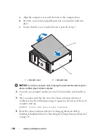
Page 161: ... properly while the computer cover is not installed Do not attempt to boot the computer before replacing the computer cover 1 Ensure that all cables are connected and fold cables out of the way Gently pull the power cables toward you so that they do not get caught underneath the drives 2 Ensure that no tools or extra parts are left inside the computer 3 Replace the cover 1 front panel release leve...

Page 162: ...rt or device and then plug it into the computer 4 Connect your computer and devices to electrical outlets and turn them on 5 After you open and close the cover the chassis intrusion detector if enabled causes the following message to appear on the screen at the next computer start up ALERT Cover was previously removed 6 Reset the chassis intrusion detector by changing Intrusion Alert to Enabled or...

Page 163: ...n this section follow the safety instructions in the Product Information Guide CAUTION To guard against electrical shock always unplug your computer from the electrical outlet before opening the cover NOTICE To prevent static damage to components inside your computer discharge static electricity from your body before you touch any of your computer s electronic components You can do so by touching ...

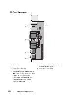
Page 164: ...rive access and network integrity lights 3 headphone connector 4 microphone connector 5 front panel thermal diode connector NOTE The front panel thermal diode cable must be installed in this connector at all times while your computer is running or thermal problems may result 2 3 4 1 5 ...

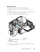
Page 165: ...ard drive carrier out of the computer see Rotating the Hard Drive Carrier Out of the Computer on page 156 4 Disconnect the card fan connector from the system board 5 If the system is in tower mode pull to remove the full length card retainer piece beside the card fan 1 card fan 2 card fan cable 3 card fan connector FAN_CCAG on system board 4 front fan 5 full length card retainer piece 3 5 2 1 4 ...

Page 166: ...ting of each cable before you disconnect it so that you are sure to re route cables correctly An incorrectly routed or a disconnected cable could lead to computer problems 7 Note the routing of each cable as you disconnect all cables attached to the I O panel 8 Remove the mounting screw from the I O panel 9 Remove the I O panel from the computer 1 I O panel 2 mounting screw 1 2 ...

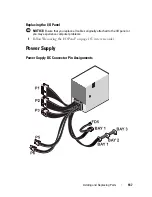
Page 167: ... I O Panel NOTICE Ensure that you replace all cables originally attached to the I O panel or you may experience computer problems 1 Follow Removing the I O Panel on page 165 in reverse order Power Supply Power Supply DC Connector Pin Assignments ...

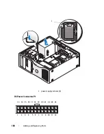
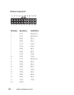
Page 168: ...168 Adding and Replacing Parts DC Power Connectors P1 1 power supply screws 4 1 13 14 15 16 17 18 19 20 21 22 23 24 1 2 3 4 5 6 7 8 9 10 11 12 ...

Page 169: ...V Orange 4 COM Black 5 POK Gray 6 5VSB Purple 7 COM Black 8 M12 Blue 9 12 VD Yellow White 10 5 V Red 11 5 V Red 12 COM Black 13 OPEN 14 3 3 VSE Orange 15 3 3 V Orange 16 12 VD Yellow White 17 PSON Green 18 12 VD Yellow White 19 COM Black 20 COM Black 21 FAN FAULT Brown 22 5 V Red 23 5 V Red 24 COM Black ...

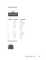
Page 170: ...12 VC Blue White 3 COM Black 4 COM Black 5 12 VA Yellow 6 12 VA Yellow 7 COM Black 8 COM Black 9 12 VB White 10 12 VB White 11 12 VC Blue White 12 COM Black 13 COM Black 14 COM Black 15 12 VA Yellow 16 COM Black 17 COM Black 18 COM Black 19 12 VB White 20 OPEN 7 8 9 10 1 2 3 4 5 6 67 68 69 20 11 12 13 14 15 66 ...

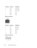
Page 171: ...Power Connector P5 Pin Number Signal name 18 AWG Wire 1 COM Black 2 12 VC Blue White 3 12 VC Blue White 4 COM Black 5 COM Black 6 5 V Red 7 5 V Red 8 3 3 V Orange 9 12 VC Blue White 10 COM Black 11 COM Black 12 5 V Red 7 8 9 10 11 12 1 2 3 4 5 6 4 5 6 1 2 3 ...

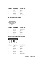
Page 172: ... Pin Number Signal name 18 AWG Wire 1 12 VD Yellow White 2 12 VD Yellow White 3 12 VD Yellow White 4 COM Black 5 COM Black 6 COM Black Pin Number Signal name 18 AWG Wire 1 12 VE Blue Yellow 2 12 VE Blue Yellow 3 12 VE Blue Yellow 4 COM Black 5 COM Black 6 COM Black 4 5 6 1 2 3 ...

Page 173: ... 3 SATA Pin Number Signal name 18 AWG Wire 1 5 V Red 2 COM Black 3 COM Black 4 12 VC Blue White Pin Number Signal name 18 AWG Wire 1 12 VC Blue White 2 COM Black 3 COM Black 4 5 V Red Pin Number Signal name 18 AWG Wire 1 3 3 V Orange 2 COM Black 3 5V Red 4 COM Black 5 12 VC Blue White 5 4 3 2 1 ...

Page 174: ...r NOTICE To prevent static damage to components inside your computer discharge static electricity from your body before you touch any of your computer s electronic components You can do so by touching an unpainted metal surface on the computer 1 Follow the procedures in Before You Begin on page 151 2 Remove the computer cover See Removing the Computer Cover on page 153 3 Disconnect the cables from...

Page 175: ...nd Replacing Parts 175 5 Slide the power supply toward the front of the computer by approximately one inch 6 Lift the power supply out of the computer 1 power supply screws 4 2 power cable harness connector 1 2 ...

Page 176: ...n Battery CAUTION Before you begin any of the procedures in this section follow the safety instructions in the Product Information Guide CAUTION To guard against electrical shock always unplug your computer from the electrical outlet before opening the cover CAUTION A new battery can explode if it is incorrectly installed Replace the battery only with the same or equivalent type recommended by the...

Page 177: ...system setup program see System Setup on page 89 If the date and time are not correct in system setup replace the battery You can operate your computer without a battery however without a battery the configuration information is erased if the computer is turned off or unplugged from the electrical outlet In this case you must enter the system setup program see System Setup on page 89 and reset the...

Page 178: ...down firmly on the positive side of the connector 7 While supporting the battery connector press the battery tab away from the positive side of the connector and pry the battery up out of the securing tabs at the negative side of the connector NOTICE To avoid damage to the battery connector you must firmly support the connector while replacing the battery 8 Support the battery connector by pressin...

Page 179: ...this section follow the safety instructions in the Product Information Guide CAUTION To guard against electrical shock always unplug your computer from the electrical outlet before opening the cover NOTICE To prevent static damage to components inside your computer discharge static electricity from your body before you touch any of your computer s electronic components You can do so by touching an...

Page 180: ... you need a long Phillips screwdriver 5 Loosen the four captive screws on the sides of the heat sink assembly CAUTION The heat sink assembly may become very hot during normal operation Ensure that it has had sufficient time to cool before you touch it 6 Lift to remove the heat sink assembly from the computer ...

Page 181: ...in which your replacement kit was sent If you are not installing a processor upgrade kit from Dell reuse the original heat sink assembly when you install your new processor 7 Open the processor cover by sliding the release lever from under the center cover latch on the socket Then pull the lever back to release the processor 1 heat sink assembly 2 captive screw housing 4 1 2 ...

Page 182: ...lease position so that the socket is ready for the new processor See Installing the Processor on page 183 Otherwise continue with step 10 10 Close the processor access door 11 Ensure that all connectors are properly cabled and firmly seated 12 Rotate the hard drive carrier back into place see Rotating the Hard Drive Carrier Back into the Computer on page 159 13 Replace the computer cover see Repla...

Page 183: ... carrier out of the computer see Rotating the Hard Drive Carrier Out of the Computer on page 156 4 Rotate the processor access door to its open position 5 If you are replacing a processor remove the processor see Removing the Processor on page 179 6 Unpack the new processor being careful not to touch the underside of the processor NOTICE You must position the processor correctly in the socket to a...

Page 184: ... Orient the front and rear alignment notches on the processor with the front and rear alignment notches on the socket 9 Align the pin 1 corners of the processor and socket 1 processor cover 2 processor 3 socket 4 release lever 1 2 3 4 ...

Page 185: ...orrectly 11 When the processor is fully seated in the socket close the processor cover Ensure that the tab on the processor cover is positioned underneath the center cover latch on the socket 12 Pivot the socket release lever back toward the socket and snap it into place to secure the processor 1 tab 2 processor socket 3 center cover latch 4 socket release lever 5 front alignment notch 6 socket an...

Page 186: ...assembly and processor to Dell in the same package in which your replacement kit was sent 13 Install the heat sink assembly a Place the heat sink assembly back onto the heat sink assembly bracket b Rotate the heat sink assembly down towards the computer base and tighten the four capture screws NOTICE Ensure that the heat sink assembly is correctly seated and secure 14 Close the processor access do...

Page 187: ...pecifications on page 36 NOTICE Before you install new memory modules download the most recent BIOS for your computer from the Dell Support website at support dell com NOTE Memory purchased from Dell is covered under your computer warranty Fully Buffered DIMM FBD Memory Overview For optimal performance fully buffered DIMMs FBDs should be installed in matched sets of four This enables quad channel ...

Page 188: ... first installed into slots DIMM_1 and DIMM_2 then DIMM_3 and DIMM_4 and so on NOTICE Do not install non ECC or unbuffered memory modules Doing so may cause the computer not to boot NOTE DIMM slots 1 4 have white latches for easy identification DIMM slot 5 8 have black latches Addressing Memory With 4 GB or Greater Configurations 32 bit Operating Systems Only This computer supports a maximum of 32...

Page 189: ...or use only by the operating system If the total installed computer memory is equal to or greater than the usable address space a portion of installed memory is not available for use by the operating system Removing Memory CAUTION Before you begin any of the procedures in this section follow the safety instructions in the Product Information Guide NOTICE If you remove your original memory modules ...

Page 190: ...uch them 4 Press out the securing clip at each end of the memory module connector 5 Grasp the module and pull up to lift the memory module from the memory riser card If a module is difficult to remove gently ease it back and forth to remove it from the connector 6 Rotate the hard drive carrier back into place see Rotating the Hard Drive Carrier Back into the Computer on page 159 7 Replace the comp...

Page 191: ...ove the computer cover see Removing the Computer Cover on page 153 3 Rotate the hard drive carrier out of the computer see Rotating the Hard Drive Carrier Out of the Computer on page 156 4 If you are replacing a memory module see Removing Memory on page 189 CAUTION Fully buffered memory modules may become very hot during normal operation Ensure that memory modules have had sufficient time to cool ...

Page 192: ...s into position If you insert the module correctly the securing clips snap into the cutouts at each end of the module 8 Rotate the hard drive carrier back into place see Rotating the Hard Drive Carrier Back into the Computer on page 159 9 Replace the computer cover see Replacing the Computer Cover on page 161 10 Connect your computer and devices to electrical outlets and turn them on 1 cutouts 2 2...

Page 193: ...etup 14 Run the Dell Diagnostics see Dell Diagnostics on page 136 to verify that the memory modules are operating properly Cards CAUTION Before you begin any of the procedures in this section follow the safety instructions in the Product Information Guide CAUTION To guard against electrical shock always unplug your computer from the electrical outlet before opening the cover NOTICE To prevent stat...

Page 194: ... replacing a PCI PCI Express or PCI X card see Removing an Expansion Card on page 201 Before installing a card see the documentation that came with the card for information on configuring the card making internal connections or otherwise customizing it for your computer If you are replacing a card uninstall the existing driver for the card Installing an Expansion Card 1 Follow the procedures in Be...

Page 195: ...Adding and Replacing Parts 195 5 If you are installing a new card remove the filler bracket to create a card slot opening Then continue with step 7 1 card retention door 2 release tab 2 1 ...

Page 196: ...he card If the card is not removed correctly the system board may be damaged 1 release tab 2 card retention door 3 alignment bar 4 alignment guide NOTE For extra security remove the alignment guide an upside down screw and screw it in right side up to secure a card 5 filler bracket 2 5 4 3 1 ...

Page 197: ...ation on configuring the card making internal connections or otherwise customizing it for your computer CAUTION Some network adapters automatically start the computer when they are connected to a network To guard against electrical shock be sure to unplug your computer from its electrical outlet before installing any cards 8 If the card is full length align it between the plastic card guides on th...

Page 198: ...lush with the alignment bar The notch in the top of the card or filler bracket fits around the alignment guide NOTE For extra security remove the alignment guide an upside down screw and screw it in right side up to secure a card 1 card fully seated 2 card not fully seated 3 bracket within slot 4 bracket caught outside of slot 1 2 4 3 ...

Page 199: ...use damage to the equipment 13 Connect any cables that should be attached to the card See the documentation for the card for information about the card s cable connections 14 If the card was installed in a slot close to the hard drive carrier check to see if there are any cables or other protrusions that might block the card retention mechanism from being lowered completely If this is the case 1 c...

Page 200: ...he card retention mechanism 15 Rotate the hard drive carrier back into the computer see Rotating the Hard Drive Carrier Out of the Computer on page 156 16 Ensure that all connectors are properly cabled and firmly seated NOTICE To connect a network cable first plug the cable into the network device and then plug the cable into the computer 17 Replace the computer cover see Replacing the Computer Co...

Page 201: ...d NIC and then change the setting to Off b Connect the network cable to the network adapter cards connectors Do not connect the network cable to the network connector on the back panel 20 Install any drivers required for the card as described in the card documentation Removing an Expansion Card 1 Follow the procedures in Before You Begin on page 151 2 Remove the computer cover see Removing the Com...

Page 202: ...ry disconnect any cables connected to the card 1 release tab 2 card retention door 3 alignment bar 4 alignment guide NOTE For extra security remove the alignment guide an upside down screw and screw it in right side up to secure a card 5 filler bracket 2 5 4 3 1 ...

Page 203: ...the empty card slot opening NOTE Installing filler brackets over empty card slot openings is necessary to maintain FCC certification of the computer The brackets also keep dust and dirt out of your computer 7 Before you close the card retention door ensure that The tops of all cards and filler brackets are flush with the alignment bar The notch in the top of each card or filler bracket fits around...

Page 204: ...outed over the cards can prevent the computer cover from closing properly or cause damage to the equipment 9 Connect any cables that should be attached to the card See the documentation for the card for information about the card s cable connections 10 Ensure that all connectors are properly cabled and firmly seated 1 card retention door 2 release tab 1 2 ...

Page 205: ...moved a sound card a Enter the system setup program see System Setup on page 89 select Integrated Audio and then change the setting to On b Connect external audio devices to the audio connectors on the back panel of the computer 15 If you removed a network adapter card a Enter the system setup program see System Setup on page 89 select Integrated NIC and then change the setting to On 16 Connect th...

Page 206: ...rive and one floppy drive or Media Card Reader Up to two hard drives up to two optical drives and one floppy drive or one Media Card Reader 1 upper 5 25 inch drive bay holds an optical drive 2 lower 5 25 inch drive bay holds optional optical drive 3 FlexBay holds optional third hard drive floppy drive or Media Card Reader 4 rotatable hard drive carrier holds two SAS or SATA drives 1 3 4 2 ...

Page 207: ...e installed in the appropriate bays at all times NOTICE If metal shields are present in your computer configuration they must be installed at all times while your computer is in use or your computer may not function properly 1 upper 5 25 inch drive bay holds an optical drive 2 lower 5 25 inch drive bay holds optional optical drive or SATA hard drive 3 rotatable hard drive carrier holds two SAS or ...

Page 208: ...nted metal shield must be installed in front of the hard drive in the FlexBay If a metal shield is installed in the 5 25 inch drive bay and you install an optical drive in its place a shield is not needed in that bay In either of the above situations the metal shield should be kept in case it is needed later If you remove a floppy drive a Media Card Reader or an optical drive from your computer yo...

Page 209: ... back of the drive The other end of the data cable will connect to either an expansion card or to the system board Most connectors are keyed for correct insertion that is a notch or a missing pin on one connector matches a tab or a filled in hole on the other connector Power Cable Connectors When connecting a data cable hold the cable by the connector at each end and press firmly into the connecto...

Page 210: ...210 Adding and Replacing Parts SATA Data Cable Connectors 1 SATA data cable 2 SATA connector on system board 3 SATA drive SATA data cable 1 2 3 4 ...

Page 211: ...Adding and Replacing Parts 211 SAS Data Cable Connectors 1 SAS data cable 2 power cable 3 SAS connector 4 SAS drive 2 1 3 4 ...

Page 212: ...ening the cover NOTICE To prevent static damage to components inside your computer discharge static electricity from your body before you touch any of your computer s electronic components You can do so by touching an unpainted metal surface on the computer NOTICE To avoid damage to the hard drive do not set it on a hard surface Instead set the drive on a surface such as a foam pad that will suffi...

Page 213: ...t you are removing 5 Disconnect the data cable from the hard drive that you are removing Do not disconnect the data cable for an uninstalled hard drive from the system board 6 Rotate the hard drive carrier out of the computer see Rotating the Hard Drive Carrier Back into the Computer on page 159 7 Press the blue tabs on each side of the hard drive bracket toward each other and slide the drive up a...

Page 214: ...drive carrier back into place see Rotating the Hard Drive Carrier Back into the Computer on page 159 10 Replace the computer cover see Replacing the Computer Cover on page 161 NOTICE To connect a network cable first plug the cable into the network port or device and then plug it into the computer 11 Connect the computer and devices to electrical outlets and turn them on 1 blue tabs 2 2 hard drive ...

Page 215: ...is procedure 2 Unpack the replacement hard drive and prepare it for installation 3 Check the documentation for the hard drive to verify that the drive is configured for your computer 4 Follow the procedures in Before You Begin on page 151 5 Remove the computer cover see Removing the Computer Cover on page 153 6 Rotate the hard drive carrier out of the computer see Rotating the Hard Drive Carrier O...

Page 216: ...e drives in the hard drive carrier must both be either SATA or SAS hard drives 9 Slide the hard drive into the hard drive bay until it clicks securely into place 10 Connect a power cable to the hard drive 11 If you are installing a SATA hard drive connect the data cable to the hard drive 1 drive 2 hard drive bracket 1 2 ...

Page 217: ...into the Computer on page 159 14 Replace the computer cover see Replacing the Computer Cover on page 161 NOTICE To connect a network cable first plug the cable into the network port or device and then plug it into the computer 15 Connect the computer and devices to electrical outlets and turn them on See the documentation that came with the drive for instructions on installing any software require...

Page 218: ...r Computer Only CAUTION Before you begin any of the procedures in this section follow the safety instructions in the Product Information Guide CAUTION To guard against electrical shock always unplug your computer from the electrical outlet before opening the cover NOTICE To prevent static damage to components inside your computer discharge static electricity from your body before you touch any of ...

Page 219: ...r your computer may not function properly 5 If metal shields are present in your computer see About the Metal Shields Present in Some Drive Configurations on page 207 slide the sliding plate lever to the right and hold it in place as you pull to remove the vented metal insert from the FlexBay 6 Disconnect the power cable from the back of the hard drive 2 3 4 5 6 1 ...

Page 220: ...release the shoulder screw and slide the drive out of the FlexBay 9 Set the drive aside in a secure location NOTICE If metal shields are present in your computer configuration they must be installed at all times while your computer is in use or your computer may not function properly 1 sliding plate lever 2 SATA data cable 3 power cable 4 power supply 5 SATA connector on system board 6 optional SA...

Page 221: ...cable first plug the cable into the network port or device and then plug it into the computer 14 Connect the computer and devices to electrical outlets and turn them on Installing an Optional Third Hard Drive Tower Computer Only CAUTION Before you begin any of the procedures in this section follow the safety instructions in the Product Information Guide CAUTION To guard against electrical shock al...

Page 222: ...mputer is in use or your computer may not function properly 6 If the FlexBay is not populated and metal shields are present in your computer see About the Metal Shields Present in Some Drive Configurations on page 207 for more information slide the sliding plate lever to the right and hold it in place as you pull to remove the vented metal insert from the FlexBay 7 If you already have a floppy dri...

Page 223: ...er cable to the back of the hard drive 11 Connect a data cable to the back of the hard drive and if it is a SATA drive connect the other end to the SATA_2 connector on the system board 1 sliding plate lever 2 optional third hard drive in FlexBay 1 2 ...

Page 224: ...ction properly 12 If metal shields are present in your computer install the vented metal insert over the FlexBay and the empty space beneath it see About the Metal Shields Present in Some Drive Configurations on page 207 for more information 1 sliding plate lever 2 SATA data cable 3 power cable 4 power supply 5 SATA connector on system board 6 optional SATA hard drive in FlexBay 2 3 4 5 6 1 ...

Page 225: ... operation 17 If the drive you just installed is the primary drive insert bootable media into drive A 18 Turn on the computer 19 Enter the system setup program see System Setup on page 89 and update the appropriate Drive option 20 Exit the system setup program and reboot the computer 21 Partition and logically format your drive before you proceed to the next step See the documentation for your ope...

Page 226: ...moving the Drive Panel on page 233 4 Pull the desktop drive retention insert out by the handle and set it aside in a safe place 5 Disconnect the power cable from the back of the hard drive 1 desktop drive retention insert 2 power cable 3 SATA data cable 4 SATA connector on system board 5 optional third SATA hard drive in hard drive carrier 2 3 4 5 1 ...

Page 227: ...9 Set the drive and carrier aside in a secure location 10 Ensure that all connectors are properly cabled and firmly seated NOTICE If metal shields are present in your computer configuration they must be installed at all times while your computer is in use or your computer may not function properly 11 If you are not installing another drive in the drive bay install a drive panel insert see Replacin...

Page 228: ...s and turn them on Installing an Optional Third SATA Hard Drive Desktop Only CAUTION Before you begin any of the procedures in this section follow the safety instructions located in the Product Information Guide CAUTION To guard against electrical shock always unplug your computer from the electrical outlet before removing the cover NOTICE In order to install a third SATA hard drive in one of the ...

Page 229: ... unpopulated and metal shields are present in your computer see About the Metal Shields Present in Some Drive Configurations on page 207 pull to remove the 5 25 inch metal shield Then remove the drive panel insert from a 5 25 inch drive bay see Removing a Drive Panel Insert on page 235 8 Flex the hard drive bracket open and align the side holes in the hard drive with the plastic pins on the bracke...

Page 230: ...rive in the hard drive bracket into the hard drive carrier 10 Slide the hard drive carrier into the 5 25 inch drive bay until it is securely seated 1 hard drive 2 hard drive bracket 1 hard drive carrier 2 SATA hard drive in hard drive bracket 2 1 2 1 ...

Page 231: ...ing Parts 231 11 Replace the desktop drive retention insert and fold down its handle 12 Connect a power cable to the hard drive 1 desktop drive retention insert 2 optional third SATA hard drive in hard drive carrier 2 1 ...

Page 232: ...e that all connectors are properly cabled and firmly seated 15 Reinstall the drive panel see Replacing the Drive Panel on page 237 16 Replace the computer cover see Replacing the Computer Cover on page 161 1 power cable 2 SATA data cable 3 SATA connector on system board 4 optional third SATA hard drive in hard drive carrier 1 2 3 4 ...

Page 233: ...propriate Drive option 21 Exit system setup and reboot the computer 22 Partition and logically format your drive before you proceed to the next step 23 See the documentation for your operating system for instructions Drive Panels CAUTION Before you begin any of the procedures in this section follow the safety instructions located in the Product Information Guide CAUTION To guard against electrical...

Page 234: ...234 Adding and Replacing Parts 1 drive panel 2 sliding plate 3 sliding plate lever 1 2 3 Tower Orientation ...

Page 235: ...e panel inserts may contain screws on the inside You can attach the screws to new drives that do not have any screws 1 Follow the procedures in Before You Begin on page 151 2 Remove the computer cover see Removing the Computer Cover on page 153 3 Remove the drive panel see Removing the Drive Panel on page 233 1 sliding plate 2 sliding plate lever 3 drive panel 3 1 2 Desktop Orientation ...

Page 236: ...the drive panel insert release tabs and rotate the insert just enough to free the release tabs 5 Slide the drive panel insert tab out from the tab slot 6 Set the drive panel insert aside in a secure location Replacing a Drive Panel Insert 1 Slide the drive panel insert tab into the drive panel slot 1 drive panel 2 drive panel insert 3 drive panel insert release tabs 2 4 drive panel insert tab in t...

Page 237: ...rive panel insert into place 3 Ensure that the drive panel insert is correctly seated in the drive panel Replacing the Drive Panel 1 Follow the procedures in Before You Begin on page 151 1 drive panel 2 drive panel insert 3 drive panel insert release tabs 2 4 drive panel insert tab in tab slot 1 2 3 4 ...

Page 238: ...238 Adding and Replacing Parts 1 drive panel tabs 2 drive panel 2 Tower Orientation 1 ...

Page 239: ...he Front Panel on page 160 5 Replace the computer cover see Replacing the Computer Cover on page 161 Floppy Drive CAUTION Before you begin any of the procedures in this section follow the safety instructions in the Product Information Guide CAUTION To guard against electrical shock always unplug your computer from the electrical outlet before opening the cover 1 drive panel 2 drive panel tabs 1 2 ...

Page 240: ... NOTE If you are adding a floppy drive to your desktop computer see Installing a Floppy Drive Desktop Computer on page 250 Removing a Floppy Drive Tower Computer 1 Follow the procedures in Before You Begin on page 151 2 Remove the computer cover see Removing the Computer Cover on page 153 3 Remove the drive panel see Removing the Drive Panel on page 233 4 Disconnect the power and data cables from ...

Page 241: ...rts 241 6 Slide the sliding plate lever to the right to release the shoulder screw and slide the drive out of the FlexBay 1 sliding plate lever 2 data cable 3 power cable 4 floppy drive connector DSKT on system board 2 3 4 1 ...

Page 242: ...figurations on page 207 install the vented metal insert over the FlexBay and the empty space beneath it a Insert the metal insert s two upper screws and its two lower screws into the corresponding slots inside the FlexBay b Push the vented metal insert until it clicks into place and its metal tabs rest flush against the chassis surface Install a drive panel insert see Replacing a Drive Panel Inser...

Page 243: ...ving the Computer Cover on page 153 3 Remove the drive panel see Removing the Drive Panel on page 233 4 If another device is installed in the FlexBay remove that device see the appropriate removal instructions in this section NOTICE If metal shields are present in your computer configuration they must be installed at all times while your computer is in use or your computer may not function properl...

Page 244: ...244 Adding and Replacing Parts 8 Gently slide the drive into the FlexBay until you hear a click or feel the drive securely installed 1 floppy drive 2 screws 4 1 2 2 1 ...

Page 245: ...rd connector labeled DSKT To locate the system board connector see System Board Components on page 28 11 Check all cable connections and fold cables out of the way to allow for airflow between the fan and cooling vents 1 sliding plate lever 2 floppy drive 1 data cable 2 power cable 3 floppy drive system board connector DSKT on system board 1 2 3 ...

Page 246: ...y software required for drive operation 16 Enter the system setup program see System Setup on page 89 and select the appropriate Diskette Drive option 17 Verify that your computer works correctly by running the Dell Diagnostics See Dell Diagnostics on page 136 Removing a Floppy Drive Desktop Computer 1 Follow the procedures in Before You Begin on page 151 2 Remove the computer cover see Removing t...

Page 247: ...Adding and Replacing Parts 247 6 Pull the desktop drive retention insert by the handle and set it aside in a safe place 1 power cable 2 data cable 3 floppy drive connector DSKT on system board 1 2 3 ...

Page 248: ...y space beneath it a Holding the metal insert at an angle insert its two upper screws into the slot that runs along the inside of the FlexBay b Rotate the bottom of the vented metal insert down and insert its two bottom screws into the slot in the open area beneath the FlexBay c Push the vented metal insert until it clicks into place and its metal tabs rest flush against the chassis surface Then i...

Page 249: ...he drive panel see Replacing the Drive Panel on page 237 12 Ensure that all connectors are properly cabled and firmly seated 13 Replace the computer cover see Replacing the Computer Cover on page 161 NOTICE To connect a network cable first plug the cable into the network port or device and then plug it into the computer 14 Connect the computer and devices to electrical outlets and turn them on 1 F...

Page 250: ... Panel on page 233 4 Pull the desktop drive retention insert by the handle and set it aside in a safe place 5 If another device is installed in the FlexBay remove that device see the appropriate removal instructions in this section NOTICE If metal shields are present in your computer configuration they must be installed at all times while your computer is in use or your computer may not function p...

Page 251: ...ented metal insert forward until its surface is flush with that of the surrounding chassis b Rotate the bottom of the metal insert up towards you disengaging its lower screws from the surrounding metal c Lift the metal insert from the computer disengaging its top screws and metal tabs from the surrounding metal 7 Remove the FlexBay drive panel insert see Removing a Drive Panel Insert on page 235 1...

Page 252: ...to the new drive 9 Gently slide the drive into the FlexBay until you hear a click or feel the drive securely installed 10 Attach the power and data cables to the floppy drive 11 Connect the other end of the data cable to the system board connector labeled DSKT To locate the system board connector see System Board Components on page 28 1 drive 2 screws 1 2 ...

Page 253: ...s 14 Reinstall the drive panel see Replacing the Drive Panel on page 237 15 Ensure that all connectors are properly cabled and firmly seated 16 Replace the computer cover see Replacing the Computer Cover on page 161 NOTICE To connect a network cable first plug the cable in to the network port or device and then plug it in to the computer 1 power cable 2 data cable 3 floppy drive connector DSKT on ...

Page 254: ...tic damage to components inside your computer discharge static electricity from your body before you touch any of your computer s electronic components You can do so by touching an unpainted metal surface on the computer NOTE If you are adding a Media Card Reader to your tower computer see Installing a Media Card Reader Tower Computer on page 257 NOTE If you are adding a Media Card Reader to your ...

Page 255: ...6 Slide the sliding plate lever to the right to release the shoulder screw and slide the reader out of the FlexBay 1 sliding plate lever 2 interface cable 3 Media Card Reader connector USB on system board 4 Media Card Reader 2 3 4 1 ...

Page 256: ...e About the Metal Shields Present in Some Drive Configurations on page 207 reinstall the vented metal insert over the FlexBay and the empty space beneath it a Insert the metal insert s two upper screws and its two lower screws into the corresponding slots inside the FlexBay b Push the vented metal insert until it clicks into place and its metal tabs rest flush against the chassis surface Then inst...

Page 257: ...e You Begin on page 151 2 Remove the computer cover see Removing the Computer Cover on page 153 3 Remove the drive panel see Removing the Drive Panel on page 233 4 If another device is installed in the FlexBay remove that device see the appropriate removal instructions in this section NOTICE If metal shields are present in your computer configuration they must be installed at all times while your ...

Page 258: ...ding and Replacing Parts 8 Gently slide the reader into the FlexBay until you hear a click or feel the reader securely installed 1 Media Card Reader 2 screws 1 sliding plate lever 2 Media Card Reader 1 2 2 1 ...

Page 259: ...s on page 28 11 Check all cable connections and fold cables out of the way to allow for airflow between the fan and cooling vents 12 Reinstall the drive panel see Replacing the Drive Panel on page 237 13 Ensure that all connectors are properly cabled and firmly seated 14 Replace the computer cover see Replacing the Computer Cover on page 161 1 interface cable 2 Media Card Reader connector USB on s...

Page 260: ...opriate USB for Flexbay option 17 Verify that your computer works correctly by running the Dell Diagnostics See Dell Diagnostics on page 136 for instructions Removing a Media Card Reader Desktop Computer 1 Follow the procedures in Before You Begin on page 151 2 Remove the computer cover see Removing the Computer Cover on page 153 3 Remove the drive panel see Removing the Drive Panel on page 233 4 ...

Page 261: ...nd Replacing Parts 261 6 Pull the desktop drive retention insert out by the handle and set it aside in a safe place 1 interface cable 2 Media Card Reader connector USB on system board 3 Media Card Reader 1 3 2 ...

Page 262: ...eneath it a Holding the metal insert at an angle insert its two upper screws into the slot that runs along the inside of the FlexBay b Rotate the bottom of the vented metal insert down and insert its two bottom screws into the slot in the open area beneath the FlexBay c Push the vented metal insert until it clicks into place and its metal tabs rest flush against the chassis surface Then install a ...

Page 263: ...drive panel see Replacing the Drive Panel on page 237 12 Ensure that all connectors are properly cabled and firmly seated 13 Replace the computer cover see Replacing the Computer Cover on page 161 NOTICE To connect a network cable first plug the cable into the network port or device and then plug it into the computer 14 Connect the computer and devices to electrical outlets and turn them on 1 Flex...

Page 264: ...anel on page 233 4 Pull the desktop drive retention insert out by the handle and set it aside in a safe place 5 If another device is installed in the FlexBay remove that device see the appropriate removal instructions in this section NOTICE If metal shields are present in your computer configuration they must be installed at all times while your computer is in use or your computer may not function...

Page 265: ...ll the vented metal insert forward until its surface is flush with that of the surrounding chassis b Rotate the bottom of the metal insert up towards you disengaging its lower screws from the surrounding metal c Lift the metal insert from the computer disengaging its top screws and metal tabs from the surrounding metal 7 Remove the FlexBay drive panel insert see Removing a Drive Panel Insert on pa...

Page 266: ...new Media Card Reader 9 Gently slide the reader into place until you hear a click or feel the drive securely installed 10 Attach the interface cable to the Media Card Reader 11 Connect the other end of the interface cable to the system board connector labeled USB To locate the system board connector see System Board Components on page 28 1 drive 2 screws 1 2 ...

Page 267: ...install the drive panel see Replacing the Drive Panel on page 237 15 Ensure that all connectors are properly cabled and firmly seated 16 Replace the computer cover see Replacing the Computer Cover on page 161 NOTICE To connect a network cable first plug the cable in to the network port or device and then plug it in to the computer 1 interface cable 2 Media Card Reader connector USB on system board...

Page 268: ...ormation Guide CAUTION To guard against electrical shock always unplug your computer from the electrical outlet before opening the cover NOTICE To prevent static damage to components inside your computer discharge static electricity from your body before you touch any of your computer s electronic components You can do so by touching an unpainted metal surface on the computer Removing an Optical D...

Page 269: ...ide the sliding plate lever to the right to release the shoulder screw and slide the drive out to remove it from the drive bay 1 optical drive 2 SATA data cable 3 power cable 4 SATA data cable 5 SATA connector on system board 3 2 43 5 1 ...

Page 270: ...s on page 207 a Install the 5 25 inch metal shield in its place align its screws in the metal rails and push the shield back until it clicks into place NOTE A metal shield for the optical drive bay can be ordered from Dell See Contacting Dell on page 295 b Install a drive panel insert over its drive bay see Replacing a Drive Panel Insert on page 236 8 If you are installing another drive in the opt...

Page 271: ...oving the Computer Cover on page 153 4 Remove the drive panel see Removing the Drive Panel on page 233 5 If another device is installed in the optical drive bay remove that device see Removing an Optical Drive Tower Computer on page 268 NOTICE If metal shields are present in your computer configuration they must be installed at all times while your computer is in use or your computer may not funct...

Page 272: ...272 Adding and Replacing Parts 9 Gently slide the drive into place until you hear a click or feel the drive securely installed 1 optical drive 2 screws 1 drive retention insert 2 optical drive 1 2 1 2 ...

Page 273: ...he data cable to a SATA connector on the system board 11 Check all cable connections and fold cables out of the way to allow for airflow between the fan and cooling vents 12 Reinstall the drive panel see Replacing the Drive Panel on page 237 1 optical drive 2 SATA data cable 3 power cable 4 SATA data cable 5 SATA connector on system board 3 2 4 5 1 ...

Page 274: ...ired for drive operation 16 Enter the system setup program see System Setup on page 89 and select the appropriate Drive option 17 Verify that your computer works correctly by running the Dell Diagnostics See Dell Diagnostics on page 136 for instructions Removing an Optical Drive Desktop Computer 1 Follow the procedures in Before You Begin on page 151 2 Remove the computer cover see Removing the Co...

Page 275: ...acing Parts 275 6 Pull the desktop drive retention insert out by the handle and set it aside in a safe place 1 optical drive 2 power cable 3 SATA data cable 4 SATA data cable 5 SATA connector on system board 3 4 2 5 1 ...

Page 276: ...ive bay and metal shields are present in your computer see About the Metal Shields Present in Some Drive Configurations on page 207 a Install the 5 25 inch metal shield in its place align its screws in the metal rails and push the shield back until it clicks into place NOTE A metal shield for the optical drive bay can be ordered from Dell See Contacting Dell on page 295 b Install a drive panel ins...

Page 277: ...t plug the cable into the network port or device and then plug it into the computer 14 Connect the computer and devices to electrical outlets and turn them on Installing an Optical Drive Desktop Computer 1 Follow the procedures in Before You Begin on page 151 2 If you are installing a new drive unpack the drive and prepare it for installation Check the documentation that accompanied the drive to v...

Page 278: ... computer may not function properly 7 If the optical drive bay is unpopulated and metal shields are present in your computer see About the Metal Shields Present in Some Drive Configurations on page 207 pull to remove the 5 25 inch metal shield 8 Remove the drive panel insert see Removing a Drive Panel Insert on page 235 9 If no screws are attached to the drive remove the shoulder screws from the i...

Page 279: ... optical drive to an HDD connector on the system board or it will not function Attach SATA optical drives to the connectors labeled SATA on the system board 11 Attach the power and data cables to the optical drive If you are installing a SATA drive connect the other end of the data cable to a SATA connector on the system board 1 optical drive 2 screws 1 2 ...

Page 280: ...able connections and fold cables out of the way to allow for airflow between the fan and cooling vents 14 Reinstall the drive panel see Replacing the Drive Panel on page 237 15 Ensure that all connectors are properly cabled and firmly seated 1 power cable 2 SATA data cable 3 SATA data connector on system board 2 3 1 ...

Page 281: ... follow the safety instructions in the Product Information Guide CAUTION To guard against electrical shock always unplug your computer from the electrical outlet before opening the cover NOTICE To prevent static damage to components inside your computer discharge static electricity from your body before you touch any of your computer s electronic components You can do so by touching an unpainted m...

Page 282: ...uring normal operation Ensure that it has had sufficient time to cool before you touch it 6 Lift to remove the heat sink assembly from the computer 7 Disconnect the optional speaker connector if installed from the system board 8 Disconnect the card fan from the system board connector labeled FAN_CCAG see System Board Components on page 28 1 heat sink assembly 2 captive screw housing 4 2 1 ...

Page 283: ...nnect the Power1 and Power2 connectors from the system board see System Board Components on page 28 12 Remove the cables from the cable guide on the front fan 13 Press the tab between the card fan and the front fan towards the card fan as you lift it up and out of the computer 14 Unscrew the fan case and lift to remove it from the computer 1 card fan 2 card fan cable 3 card fan system board connec...

Page 284: ... to make sure that you have the correct part 18 Remove the nine system board screws 19 Lift the system board from the computer 20 Place the system board that you just removed next to the replacement system board Replacing the System Board 1 Transfer components from the existing system board to the replacement system board a Remove the memory modules and install them on the replacement board see Me...

Page 285: ... be in different locations than the corresponding connectors on the existing system board 3 Orient the replacement board by aligning the screw holes in the board with the corresponding holes in the computer chassis 4 Screw in the 9 screws that attach the system board 5 Replace the heat sink assembly and tighten the four captive screws to secure it to the system board 6 Replace any components and c...

Page 286: ...286 Adding and Replacing Parts ...

Page 287: ...Adding and Replacing Parts 287 ...

Page 288: ...288 Adding and Replacing Parts ...

Page 289: ...upport dell com for help with installation and troubleshooting procedures See Online Services on page 290 for a more extensive list of Dell Support online 5 If the preceding steps have not resolved the problem see Contacting Dell on page 295 NOTE Call Dell Support from a telephone near or at the computer so that the support staff can assist you with any necessary procedures NOTE Dell s Express Ser...

Page 290: ...or your region or go to support dell com Online Services You can learn about Dell products and services on the following websites www dell com www dell com ap Asian Pacific countries only www dell com jp Japan only www euro dell com Europe only www dell com la Latin American and Caribbean countries www dell ca Canada only You can access Dell Support through the following websites and e mail addres...

Page 291: ... on the status of any Dell products that you have ordered you can go to support dell com or you can call the automated order status service A recording prompts you for the information needed to locate and report on your order For the telephone number to call for your region see Contacting Dell on page 295 Problems With Your Order If you have a problem with your order such as missing parts wrong pa...

Page 292: ...ivalent packing materials You are responsible for paying shipping expenses You are also responsible for insuring any product returned and you assume the risk of loss during shipment to Dell Collect On Delivery C O D packages are not accepted Returns that are missing any of the preceding requirements will be refused at Dell s receiving dock and returned to you Before You Call NOTE Have your Express...

Page 293: ...Getting Help 293 CAUTION Before working inside your computer follow the safety instructions in your Product Information Guide ...

Page 294: ...ion Devices Expansion cards Are you connected to a network Yes No Network version and network adapter Programs and versions See your operating system documentation to determine the contents of the system s start up files If the computer is connected to a printer print each file Otherwise record the contents of each file before calling Dell Error message beep code or diagnostic code Description of ...

Page 295: ...support and service options Availability varies by country and product and some services may not be available in your area To contact Dell for sales technical support or customer service issues 1 Visit support dell com 2 Verify your country or region in the Choose A Country Region drop down menu at the bottom of the page 3 Click Contact Us on the left side of the page 4 Select the appropriate serv...

Page 296: ...296 Getting Help ...

Page 297: ...hanges or modifications not expressly approved by Dell Inc could void your authority to operate this equipment These limits are designed to provide reasonable protection against harmful interference in a residential installation However there is no guarantee that interference will not occur in a particular installation If this equipment does cause harmful interference with radio or television rece...

Page 298: ...ument in compliance with the FCC regulations Product name Dell Precision T5400 Model number DCTA Company name Dell Inc Worldwide Regulatory Compliance Environmental Affairs One Dell Way Round Rock TX 78682 USA 512 338 4400 NOTE For further regulatory information see your Product Information Guide ...

Page 299: ...e video circuitry and the computer memory AHCI Advanced Host Controller Interface An interface for a SATA hard drive Host Controller which allows the storage driver to enable technologies such as Native Command Queuing NCQ and hot plug ALS ambient light sensor A feature that helps to control display brightness antivirus software A program designed to identify quarantine and or delete viruses from ...

Page 300: ...its per second The standard unit for measuring data transmission speed BTU British thermal unit A measurement of heat output bus A communication pathway between the components in your computer bus speed The speed given in MHz that indicates how fast a bus can transfer information byte The basic data unit used by your computer A byte is usually equal to 8 bits C C Celsius A temperature measurement ...

Page 301: ...er Also referred to as the Product Key or Product ID Control Panel A Windows utility that allows you to modify operating system and hardware settings such as display settings controller A chip that controls the transfer of data between the processor and memory or between the processor and devices CRIMM continuity rambus in line memory module A special module that has no memory chips and is used to...

Page 302: ...sources DRAM dynamic random access memory Memory that stores information in integrated circuits containing capacitors driver Software that allows the operating system to control a device such as a printer Many devices do not work properly if the correct driver is not installed in the computer DSL Digital Subscriber Line A technology that provides a constant high speed Internet connection through a...

Page 303: ...er and communications equipment expansion card A circuit board that installs in an expansion slot on the system board in some computers expanding the capabilities of the computer Examples include video modem and sound cards expansion slot A connector on the system board in some computers where you insert an expansion card connecting it to the system bus ExpressCard A removable I O card adhering to...

Page 304: ...data path and physical interface between the processor and RAM FTP file transfer protocol A standard Internet protocol used to exchange files between computers connected to the Internet G G gravity A measurement of weight and force GB gigabyte A measurement of data storage that equals 1024 MB 1 073 741 824 bytes When used to refer to hard drive storage the term is often rounded to 1 000 000 000 by...

Page 305: ... video equipment IDE integrated device electronics An interface for mass storage devices in which the controller is integrated into the hard drive or CD drive IEEE 1394 Institute of Electrical and Electronics Engineers Inc A high performance serial bus used to connect IEEE 1394 compatible devices such as digital cameras and DVD players to the computer infrared sensor A port that allows you to tran...

Page 306: ...0 Hz L LAN local area network A computer network covering a small area A LAN usually is confined to a building or a few nearby buildings A LAN can be connected to another LAN over any distance through telephone lines and radio waves to form a wide area network WAN LCD liquid crystal display The technology used by portable computer and flat panel displays LED light emitting diode An electronic comp...

Page 307: ... identify information that the processor can access memory module A small circuit board containing memory chips which connects to the system board MHz megahertz A measure of frequency that equals 1 million cycles per second The speeds for computer processors buses and interfaces are often measured in MHz Mini PCI A standard for integrated peripheral devices with an emphasis on communications such ...

Page 308: ...technology to read or write data from CDs DVDs or DVD RWs Example of optical drives include CD drives DVD drives CD RW drives and CD RW DVD combo drives P parallel connector An I O port often used to connect a parallel printer to your computer Also referred to as an LPT port partition A physical storage area on a hard drive that is assigned to one or more logical storage areas known as logical dri...

Page 309: ...s the start up processor A computer chip that interprets and executes program instructions Sometimes the processor is referred to as the CPU central processing unit PS 2 personal system 2 A type of connector for attaching a PS 2 compatible keyboard mouse or keypad PXE pre boot execution environment A WfM Wired for Management standard that allows networked computers that do not have an operating sy...

Page 310: ...uter reside in ROM RPM revolutions per minute The number of rotations that occur per minute Hard drive speed is often measured in rpm RTC real time clock Battery powered clock on the system board that keeps the date and time after you shut down the computer RTCRST real time clock reset A jumper on the system board of some computers that can often be used for troubleshooting problems S SAS serial a...

Page 311: ... Interface An audio transfer file format that allows the transfer of audio from one file to another without converting it to and from an analog format which could degrade the quality of the file standby mode A power management mode that shuts down all unnecessary computer operations to save energy Strike Zone Reinforced area of the platform base that protects the hard drive by acting as a dampenin...

Page 312: ... Windows Notepad uses a text editor Text editors do not usually provide word wrap or formatting functionality the option to underline change fonts and so on TPM trusted platform module A hardware based security feature that when combined with security software enhances network and computer security by enabling features such as file and e mail protection travel module A plastic device designed to f...

Page 313: ...onsists of memory chips dedicated to video functions Video memory is usually faster than system memory The amount of video memory installed primarily influences the number of colors that a program can display video mode A mode that describes how text and graphics are displayed on a monitor Graphics based software such as Windows operating systems displays in video modes that can be defined as x ho...

Page 314: ... cannot be changed Use write protection when you want to protect data from being changed or destroyed To write protect a 3 5 inch floppy disk slide its write protect tab to the open position WWAN wireless wide area network A wireless high speed data network using cellular technology and covering a much larger geographic area than WLAN WXGA wide aspect extended graphics array A video standard for v...

Page 315: ...ve A high capacity floppy drive developed by Iomega Corporation that uses 3 5 inch removable disks called Zip disks Zip disks are slightly larger than regular floppy disks about twice as thick and hold up to 100 MB of data ...

Page 316: ...316 Glossary ...
Reviews: