4-8
Diagnostics and Troubleshooting Guide
After running particular diagnostic tests and viewing the
status messages generated by the tests in the result file,
you can erase the contents of the file so that it is clear for
the next set of messages generated. Otherwise, the next
messages are added at the end of the previous ones in the
file.
Output Device for Error Messages
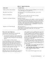
Ordinarily, all error messages appear only on the screen.
This parameter allows you to direct error messages to
either a printer or a file, in addition to the screen. If you
choose the File option, error messages are written to the
result file used for status messages. This file is automati-
cally created on a diskette that you insert into drive A
when prompted. If you are running the diagnostics from a
utility partition on your hard-disk drive, the result file is
created on the hard-disk drive. If the result file already
exists, new error messages are added to it.
The result file is an ordinary ASCII text file. You can
access and review the result file as described in the pre-
vious subsection, “Output Device for Status Messages.”
After running particular diagnostic tests and viewing the
error messages generated by the tests in the result file,
you can erase the contents of the file so that it is clear for
the next set of messages generated. Otherwise, the next
messages are added at the end of the previous ones in the
file.
Test Limits
NOTE: The Dell Diagnostics sets default limits on all
tests. The only reason to change the default would be to
limit the amount of testing done.
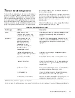
The RAM Test Group, the Video Test Group, the Diskette
Drives Test Group, the Hard-Disk Drives (Non-SCSI)
Test Group, the Serial/Infrared Ports Test Group, the Par-
allel Ports Test Group, and the SCSI Devices Test Group
allow you to designate limits. Whether you select Test
Limits for a highlighted test group (from the Main menu)
or a subtest (from the Subtest menu), you set the limits
for all the subtests in that test group. When you select
Test Limits, a new screen appears and the Key-Help area
lists keys to use with the new screen. Press <Page Down>
to select the next menu or submenu. Press <Esc> to
return to the main Test Limits window.
How you change a value for the limits of a test group or
subtest depends on the type of parameter associated with
it. Different keys are used to change values for different
types of parameters. For example, memory address limits
specified for the RAM Test Group are changed by typing
in numbers over the digits of a given limit or by pressing
the plus (+) or minus (-) keys to increase or decrease the
given limit. In contrast, to set limits for the Serial/
Infrared Ports Test Group, you use the <Spacebar> to
toggle between Yes and No.
After you are satisfied with the limits, return to the Dell
Diagnostics main screen by pressing the <Esc> key. The
values you selected under Test Limits remain in effect
during all the test groups or subtests you run, unless you
change them. However, the values are reset to their
defaults when you restart the diagnostics.
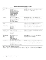
About
About in the Main menu lists all of the subtests for the
selected test group and displays information about the
subtest that is highlighted.
Key-Help
Key-Help always displays a list of key controls available
for the particular category you have selected.
Quit
Selecting Quit from the Main menu exits the diagnostics
and returns you to your operating system environment.
After you return to the operating system environment,
remove your diagnostics diskette from drive A and
reboot the computer.
CAUTION: It is important that you quit the diag-
nostics correctly because the program writes data
to the computer’s memory that can cause prob-
lems unless properly cleared.
Summary of Contents for OptiPlex HUB
Page 1: ... 1267 6 1 7528 6 227 1 8 ...
Page 2: ......
Page 3: ... 1267 6 1 7528 6 227 1 8 ...
Page 10: ...x ...
Page 18: ...xx DELL CONFIDENTIAL Preliminary 2 10 98 ...
Page 20: ...xxii DELL CONFIDENTIAL Preliminary 2 10 98 ...
Page 38: ...2 14 Diagnostics and Troubleshooting Guide ...
Page 42: ...3 4 Diagnostics and Troubleshooting Guide ...

