DESIGNER’S HANDBOOK 4189350049C EN
Page 70 of 206
Like in the example with the sin/cos potentiometer it is possible to overwrite the internal Vref by and external
supply, for example 24V, connect 0 V to terminal 1 AGND and +24V to terminal 3 (Vref).
XDi will continuously measure the voltage on the Vref terminal and calibrate the measurements accordingly. It will
even be able to eliminate slow fluctuations in the 24 V supply voltage, for example during an emergency situation
where the indicator system is powered by a 24 V battery source with a slowly dropping voltage.
5.6.9.6
Input lost detection on dual potentiometer input
On a voltage or potentiometer input 0 is often a valid value and it is therefore not directly possible to detect if the
input connection is lost since it will just create a 0 input signal. To make it possible to detect a lost connection in
such a system it can be necessary to move the active input range so that it is possible to detect when the input is
lost.
Double potentiometers
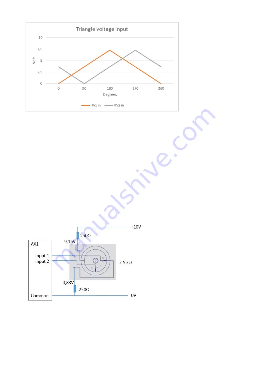
In the example below the double potentiometer configuration 2 additional resistors are used to create a minimum
and maximum voltage that is used to detect if one of the connections to the potentiometer is lost.
When you use 2 resistors as shown it is possible to detect not only if one of the inputs (or both) is lost, but also if
the connection potentiometer to 0V or +10V is lost.
This can be either a sin/cos or triangle (double linear) potentiometer.
In the example the low error voltage can be inserted as 400mV (0.4V) and the high error voltage to 9250mV
(9.25V).
In case of a double potentiometer the use of 2 resistors will balance the 0 point to ½ x 10V and that may make
calibration easier, but both for sin/cos and double triangle inputs XDi is able to detect if the difference voltage
between inputs is to low which will happen if potentiometer connection to 0V or +10V is lost. In this case the 250
Ω
resistor to 0V will be sufficient to detect if connection to one or both inputs are lost.


