DESIGNER’S HANDBOOK 4189350049C EN
Page 145 of 206
11.8.1.1
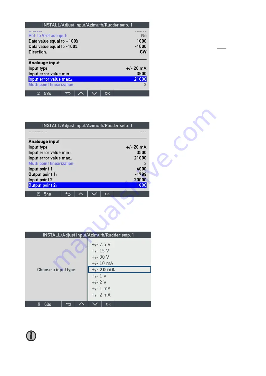
Analogue single input types
The analogue input types are shown below. Select the input type and value that best fit your application.
Detailed description is found in the chapter describing the AX1 module.
Multi-point linearisation:
indicates the
number of calibration points that are
activated for the input in this VS profile
(fixed). In this case, it is 2 point calibration
that makes 2 sets of in/out calibration
parameters active.
Note: For an azimuth 180° = -180° you
should only scale to -179.9° as shown in
this example.
Direction
is quite useful if the analogue
input is reversed in the actual installation.
But be careful using it on 4-20mA input
since it is the +/- sign on the input that is
changed when direction is changed !
Input type:
can be changed (see below).
Input error value min and max:
by
setting a valid input range between min
and max, it is possible to get an AX1 input
error message and data lost indication
when input value is outside the range.
If the input type is changed, then all used input points must be re-entered, and make sure also to edit the
input error min/max values.


