DESIGNER’S HANDBOOK 4189350049C EN
Page 146 of 206
11.8.1.2
Analogue input with multi-point linearisation
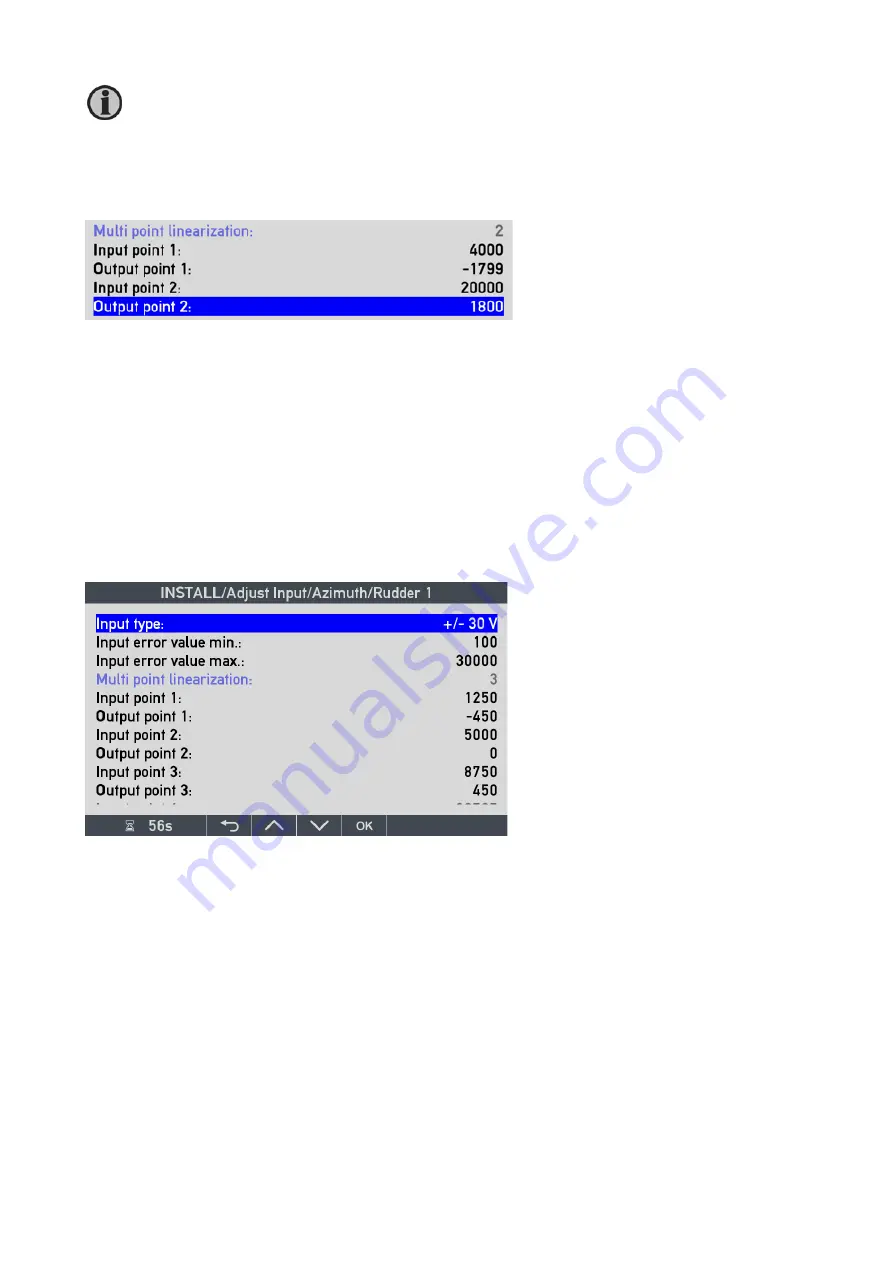
The azimuth angle input is only using 2 point linearisation (scaling) as shown below.
Input point 1:
when input type is +/-20 mA, this parameter is the input current in µA that must be equal to the
Output point 1:
in this case, the angle -1799 at the standard resolution of x0.1°.
Input point 2:
is the input current in µA equal to the
Output point 2:
in this case, the angle 1800 at the standard resolution of x0.1°.
(See also AX1 chapter)
Analogue rudder input voltage
When the analogue input is used for rudder applications, 3-point linearisation of the analogue input is normally
used. Below is a 0-10V input signal from the rudder sensor calibrated in the actual system.
In XDi it is possible to make customised VS profiles with analogue input that has up to 7-point linearisation
(see description in the AX1 chapter).
The input types are described in more details below and in the chapter regarding AX1 module.
As it can be seen in the screen picture:
This VS profile use 3 point calibration.
Input point 1
is 1250mV (1.25V), that is
equal to
Output point 1
: max PS rudder -450 (-45.0°)
In/out 2
: 5000mV (5.0V) is the centre 0° and
In/out 3
: 8750mV (8.75V) is the max SB
rudder 450 (+45.0°).


