IQ 100 Series (130/140/150)
Meter User & Installation Manual
IM02601003E Rev D
Page 1: ...IQ 100 Series 130 140 150 Meter User Installation Manual IM02601003E Rev D...
Page 2: ...NG AND INFORMATION CONTAINED THEREON IS CONFIDENTIAL AND IS THE EXCLUSIVE PROPERTY OF EATON CORPO RATION AND IS MERELY ON LOAN AND SUBJECT TO RECALL BY EATON AT ANY TIME BY TAKING POSSESSION OF THIS D...
Page 3: ...cer 11 Voltage and Current Inputs 11 Universal Voltage Inputs 11 Current Inputs 12 Ordering Information 12 Measured Values 13 Utility Peak Demand IQ140 150 14 Specifications 14 Compliance 16 Accuracy...
Page 4: ...t Panel 42 Understanding Startup and Default Displays 42 Using the Main Menu 43 Using Reset Mode 43 Entering a Password 44 Using Configuration Mode 45 Configuring the Scroll Feature 46 Configuring CT...
Page 5: ...g from an IQ 100 Series meter 65 Changing the Primary Device Address 65 Merging Connection Databases 65 Using the Options Screen 66 Using the Help Menu 66 App A IQ 100 Series Navigation Maps 67 Introd...
Page 6: ...IQ 100 Series 130 140 150 Meter Table of Contents 6 User and Installation Manual IM02601003E July 2010 www eaton com...
Page 7: ...MENTS WARRANTIES EXPRESSED OR IMPLIED INCLUDING WARRANTIES OF FITNESS FOR A PARTICULAR PURPOSE OR MERCHANTABILITY OTHER THAN THOSE SPECIFICALLY SET OUT IN ANY EXISTING CONTRACT BETWEEN THE PARTIES ANY...
Page 8: ...IQ 100 Series 130 140 150 Meter Disclaimer of Warranties and Limitation of Liability 8 User and Installation Manual IM02601003E July 2010 www eaton com...
Page 9: ...information You can also find information on local distributors or Eaton s sales offices Website Address www eaton com electrical EatonCare Customer Support Center Call the EatonCare Support Center i...
Page 10: ...our PanelMate products You will receive technical and application support For Customers in Europe contact BFA Solutions Ltd Voice 41 1 806 64 44 9 00 am 5 00 pm CET e mail gk bfa ch www bfa ch Repair...
Page 11: ...eets ANSI C12 20 0 5 Multifunction Measurement including Voltage Current Power Frequency Energy etc Field Upgrade without Removing Installed Meter Percentage of Load Bar for Analog Meter Perception Ea...
Page 12: ...inated on the meter This too eliminates any possible point of failure at the meter This is a preferred technique for insuring that relay class CT integrity is not compromised the CT will not open in a...
Page 13: ...ries Feature Comparison Readings Features IQ 130 IQ 140 IQ150 Volts L N Yes Yes Yes Volts L N Max Min Yes Yes Yes Volts L L Yes Yes Yes Volts L L Max Min Yes Yes Yes Amps Yes Yes Yes Amps Neutral Yes...
Page 14: ...nstanta neous Max and Min reading which displays the highest surge and lowest sag seen by the meter Specifications Power Supply Range 1 Option Universal 90 to 265 VAC 50 60Hz or 100 to 370 VDC 4 Optio...
Page 15: ...y A D Conversion 6 Simultaneous 24 bit Analog to Digital Converters Update Rate Watts VAR and VA 100 milliseconds Ten times per second All other parameters 1 second Communication Format 1 Optional RS4...
Page 16: ...Range Voltage L N 0 25 0 9999 V or kV Autoscale Voltage L L 0 25 0 9999 V or kV Autoscale Current Phase 0 25 0 9999 V or kV Autoscale Current Neutral Calculated 2 0 F S 0 9999 V or kV Autoscale Watts...
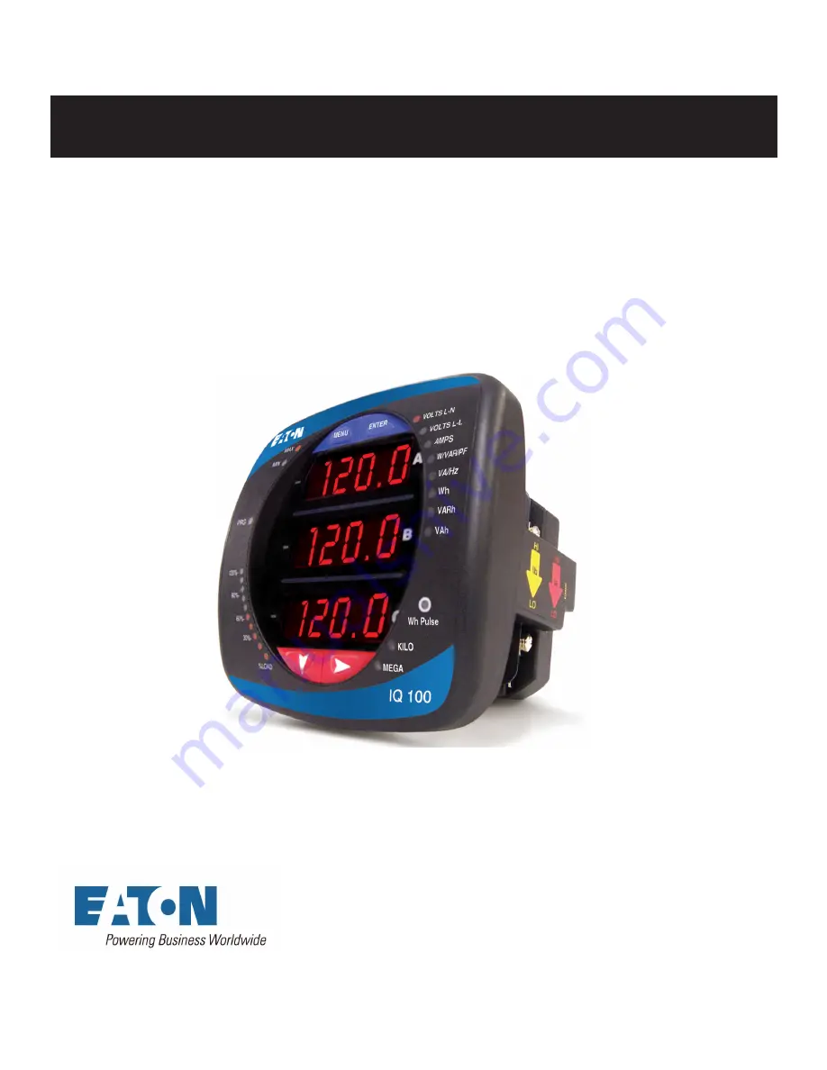
Page 17: ...100 Series meter The various models use the same installation See the next chapter for wiring diagrams Meter Face Meter Dimensions Transducer Dimensions Meter Back ANSI Mounting Panel Cut out DIN Moun...
Page 18: ...the back of meter Twist until secure 2 Slide ANSI 12 Mounting Gasket onto back of meter with rods in place 3 Slide meter with Mounting Gasket into panel 4 Secure from back of panel with lock washer an...
Page 19: ...rom back of panel slide 2 DIN Mounting Brackets into grooves in top and bottom of meter housing Snap into place 3 Secure meter to panel with lock washer and a 8 screw through each of the 2 mounting br...
Page 20: ...ION STEPS 1 Slide top groove of meter onto the DIN Rail 2 Press gently until the meter clicks into place NOTE If mounting with the DIN Rail provided use the Black Rubber Stoppers also provided TO REMO...
Page 21: ...the meter may cause harm or death Do not use the meter for any application where there may be a risk of fire All meter terminals should be inaccessible after installation Do not apply more than the m...
Page 22: ...uses Nickel Plated Brass Studs Current Gills with screws at each end This connection allows the CT wires to be terminated using either an O or a U lug Tighten the screws with a 2 Phillips screwdriver...
Page 23: ...tion The second method allows the CT wires to pass through the CT Inputs without terminating at the meter In this case remove the Current Gills and place the CT wire directly through the CT opening Th...
Page 24: ...ser and Installation Manual IM02601003E July 2010 www eaton com Quick Connect Crimp CT Terminations For Quick Termination or for Portable Applications a Quick Connect Crimp CT Connection can also be u...
Page 25: ...onnection Ground Connections The meter s Ground Terminals should be connected directly to the installation s protective earth ground Use 2 5mm wire for this connection Voltage Fuses Eaton recommends t...
Page 26: ...kup b Example of Single Phase Hookup 2 Three Phase Four Wire System Wye with Direct Voltage 2 5 Element 3 Three Phase Four Wire Wye with PTs 3 Element 4 Three Phase Four Wire Wye with PTs 2 5 Element...
Page 27: ...IQ 100 Series 130 140 150 Meter Electrical Installation User and Installation Manual IM02601003E July 2010 www eaton com 27 1a Example of Dual Phase Hookup...
Page 28: ...IQ 100 Series 130 140 150 Meter Electrical Installations 28 User and Installation Manual IM02601003E July 2010 www eaton com 1b Example of Single Phase Hookup...
Page 29: ...140 150 Meter Electrical Installation User and Installation Manual IM02601003E July 2010 www eaton com 29 2 Service 2 5 Element WYE 4 Wire with No PTs 3 CTs Select 2 5 EL WYE 2 5 Element Wye in Meter...
Page 30: ...ies 130 140 150 Meter Electrical Installations 30 User and Installation Manual IM02601003E July 2010 www eaton com 3 Service WYE 4 Wire with 3 PTs 3 CTs Select 3 EL WYE 3 Element Wye in Meter Programm...
Page 31: ...140 150 Meter Electrical Installation User and Installation Manual IM02601003E July 2010 www eaton com 31 4 Service 2 5 Element WYE 4 Wire with 2 PTs 3 CTs Select 2 5 EL WYE 2 5 Element Wye in Meter P...
Page 32: ...ies 130 140 150 Meter Electrical Installations 32 User and Installation Manual IM02601003E July 2010 www eaton com 5 Service Delta 3 Wire with No PTs 2 CTs Select 2 Ct dEL 2 CT Delta in Meter Programm...
Page 33: ...ries 130 140 150 Meter Electrical Installation User and Installation Manual IM02601003E July 2010 www eaton com 33 6 Service Delta 3 Wire with 2 PTs 2 CTs Select 2 Ct dEL 2 CT Delta in Meter Programmi...
Page 34: ...ries 130 140 150 Meter Electrical Installations 34 User and Installation Manual IM02601003E July 2010 www eaton com 7 Service Delta 3 Wire with 2 PTs 3 CTs Select 2 Ct dEL 2 CT Delta in Meter Programm...
Page 35: ...35 8 Service Current Only Measurement Three Phase Select 3 EL WYE 3 Element Wye in Meter Programming setup Even if the meter is used for only amp readings the unit requires a Voltage reference Please...
Page 36: ...com 9 Service Current Only Measurement Dual Phase Select 3 EL WYE 3 Element Wye in Meter Programming setup Even if the meter is used for only amp readings the unit requires a Voltage reference Please...
Page 37: ...37 10 Service Current Only Measurement Single Phase Select 3 EL WYE 3 Element Wye in Meter Programming setup Even if the meter is used for only amp readings the unit requires a Voltage reference Pleas...
Page 38: ...IQ 100 Series 130 140 150 Meter Electrical Installations 38 User and Installation Manual IM02601003E July 2010 www eaton com...
Page 39: ...Series meter s RS485 connection uses standard 2 Wire Half Duplex Architecture The RS485 KYZ Pulse Output connector is located on the terminal section of the meter A connection can easily be made to a...
Page 40: ...e next page No more than two cables should be connected at any one point on an RS485 network whether the connections are for devices converters or terminal strips Include all segments when calculating...
Page 41: ...IQ 100 Series 130 140 150 Meter Communication Installation User and Installation Manual IM02601003E July 2010 www eaton com 41...
Page 42: ...ont face of the meter Programming and communication utilize the RS485 connection on the back face of the meter Once a connection is established Eaton Meter Configuration Software can be used to progra...
Page 43: ...ype of Reading Parameter Designator Indicates Reading Displayed Watt Hour Test Pulse Energy Pulse Output to Test Accuracy Scaling Factor Kilo or Mega multiplier of Displayed Readings of Load Bar Graph...
Page 44: ...re with optional communication see the chapter beginning on page 53 for instructions Understanding Startup and Default Displays Upon Power Up the meter displays a sequence of screens Lamp Test Screen...
Page 45: ...NOTE With the communication option you can reset both the Max Min values and the energy accumulators If you do not have the communication option you cannot reset the energy accumulator fields Press th...
Page 46: ...rect number appears for that dash use the the Right button to move to the next dash Example The left screen below shows four dashes The right screen shows the display after the first two digits of the...
Page 47: ...CFG is in A window Parameter screen appears Press Down Press Enter when Parameter you want is in A window 6 The parameter screen appears showing the current settings To change the settings Use either...
Page 48: ...IQ130 140 or 150 To enable or disable Auto scrolling 1 Press the Enter button when SCrl is in the A window The Scroll YES screen appears 2 Press either the Right or Down button if you want to access t...
Page 49: ...ton to move to the next digit b To change the value for CT scaling from the Ct S screen Use the Right button or the Down button to choose the scaling you want The Ct S setting can be 1 10 or 100 NOTE...
Page 50: ...value for the PT scaling from the Pt S screen Use the Right button or the Down button to choose the scaling you want The Pt S setting can be 1 10 100 or 1000 NOTE If you are prompted to enter a passwo...
Page 51: ...or Modbus ASCII 1 Press the Enter button when POrt is in the A window The Adr address screen appears You can either Enter the address Access one of the other Port screens by pressing the Enter button...
Page 52: ...yed parameter has the Indicator light next to it on the right face of the meter 2 Press the Right button to view additional readings for that parameter The table below shows possible readings for Oper...
Page 53: ...t the bottom left of the IQ 100 Series front panel provides a graphic representation of Amps The segments light according to the load as shown in the Load Segment Table below When the Load is over 120...
Page 54: ...measurements are correct Since the IQ 100 Series meter is a traceable revenue meter it contains a utility grade test pulse that can be used to gate an accuracy standard This is an essential feature r...
Page 55: ...through your PC a Make sure the Serial Port radio button is selected b Enter Device Address 1 249 c Select Baud Rate from the pull down menu d Select the port you are using from the pull down menu The...
Page 56: ...Device Profile screen The tabs at the top of the screen allow you to navigate between Settings screens The Buttons at the bottom of the screen allowyou to perform tasks for example updating the Devic...
Page 57: ...the right Select the saved Device Profile you want and click Open The settings from that file will now appear in the Settings screens for example the CT and PT Ratios will be those from the saved Dev...
Page 58: ...o the meter With properly set ratios and multipliers the readings of the meter can be used to determine the energy voltage current or power of the system This setting is the first screen displayed whe...
Page 59: ...Energy Scale Unit kilo k Mega M Example Shows an example of selected settings Power Direction View as Load or View as Generator NOTES The Energy Digits Scale and Decimal Places settings determine how...
Page 60: ...to configure meter password or assign a meter designation Click the Settings tab You will see the screen shown on the right To Enable or Disable Password for Reset and or Configuration Click the chec...
Page 61: ...s accessed by clicking Real Time Poll in the Title Bar Real Time Readings Revenue Energy and Demand Readings Power Quality When you click Real Time Readings Revenue Energy and Demand Readings and Powe...
Page 62: ...a copy of the screen Click Help to view instructions for this screen Click OK to return to the main screen Poll Power and Demand Click Real Time Poll Revenue Energy and Demand Readings Power and Deman...
Page 63: ...The V Aux phasor is referenced to V A phase To adjust the Phasor display click Options at the bottom of the screen You will see the screen shown on the right a In the Display Angles Increasing and Pha...
Page 64: ...r Reset Device Information Click this option to reset either Max Min values IQ 130 IQ 140 and IQ 150 meters and or Energy Accumulators IQ 150 only You will see the screen shown on the right Click the...
Page 65: ...or more meters to which you can connect You can Add a Location and or a Device Edit a Location and or Device or Remove a Location and or Device To Add a Location a Click on the Add button You will see...
Page 66: ...d Number for example Protocol Modbus RTU ASCII or Modbus TCP Device Type IQ Meter Comm Port 1 or 2 Serial Port Only IP Address 100 10 10 10 for example Network Only Port Number 502 Default Network Onl...
Page 67: ...rate and protocol as the meter to which the computer is connected Disconnecting from an IQ 100 Series meter To disconnect from an IQ 100 Series meter or from a location do one of the following Click o...
Page 68: ...aths the Eaton Meter Configuration Software uses for data 3 Click the Data Scan Mode tab to see the second screen on the right Use this screen to select Normal Scan rate or to enter a custom Scan rate...
Page 69: ...aps for the IQ 100 Series meter s displays Navigation Maps Sheets 1 to 4 The IQ 100 Series Navigation maps begin on the next page The maps show in detail how to move from one screen to another and fro...
Page 70: ...IQ 100 Series 130 140 150 Meter App A Navigation Maps 70 User and Installation Manual IM02601003E July 2010 www eaton com...
Page 71: ...IQ 100 Series 130 140 150 Meter App A Navigation Maps User and Installation Manual IM02601003E July 2010 www eaton com 71...
Page 72: ...IQ 100 Series 130 140 150 Meter App A Navigation Maps 72 User and Installation Manual IM02601003E July 2010 www eaton com...
Page 73: ...IQ 100 Series 130 140 150 Meter App A Navigation Maps User and Installation Manual IM02601003E July 2010 www eaton com 73...
Page 74: ...IQ 100 Series 130 140 150 Meter App A Navigation Maps 74 User and Installation Manual IM02601003E July 2010 www eaton com...
Page 75: ...ase Angle Block Status Block and Minimum and Maximum readings Commands Section Registers 20000 26011 details the Meter s Resets Block Programming Block Other Commands Block and Encryption Block Progra...
Page 76: ...01D 0x0B9 Bit 7 6 5 4 3 2 1 0 7 6 5 4 3 2 1 0 7 6 5 4 3 2 1 0 7 6 5 4 3 2 1 0 Mean ing s e e e e e e e e m m m m m m m m m m m m m m m m m m m m m m m sign exponent mantissa 1 0x089 137 0b011000010001...
Page 77: ...nto the SCADA package UI are shown For example You need to display the meter s serial number in your SCADA application The meter s Modbus map shows the following information for meter serial number De...
Page 78: ...IQ 100 Series 130 140 150 Meter App B Modbus Map 78 User and Installation Manual IM02601003E July 2010 www eaton com...
Page 79: ...to 9999 M volts 2 03E9 03EA 1002 1003 Volts B N FLOAT 0 to 9999 M volts 2 03EB 03EC 1004 1005 Volts C N FLOAT 0 to 9999 M volts 2 03ED 03EE 1006 1007 Volts A B FLOAT 0 to 9999 M volts 2 03EF 03F0 1008...
Page 80: ...2009 Positive VARs 3 Ph Average FLOAT 9999 M to 9999 M VARs 2 07D9 07DA 2010 2011 Negative Watts 3 Ph Average FLOAT 9999 M to 9999 M watts 2 07DB 07DC 2012 2013 Negative VARs 3 Ph Average FLOAT 9999 M...
Page 81: ...um Avg Demand FLOAT 0 to 9999 M amps 2 0C2B 0C2C 3116 3117 Amps C Maximum Avg Demand FLOAT 0 to 9999 M amps 2 0C2D 0C2E 3118 3119 Positive Watts 3 Ph Maximum Avg Demand FLOAT 0 to 9999 M watts 2 0C2F...
Page 82: ...6 1800 to 1800 0 1 degree 1 1006 1006 4103 4103 Angle Volts A B SINT16 1800 to 1800 0 1 degree 1 1007 1007 4104 4104 Angle Volts B C SINT16 1800 to 1800 0 1 degree 1 1008 1008 4105 4105 Angle Volts C...
Page 83: ...Block Size 6 read write 61A7 61A7 25000 25000 Force Meter Restart UINT16 password5 causes a watchdog reset always reads 0 1 Block Size 1 read write 658F 659A 26000 26011 Perform a Secure Operation UIN...
Page 84: ...ettings Flags UINT16 bit mapped g nn srp wf g enable alternate full scale bargraph current 1 on 0 off nn number of phases for voltage current screens 3 ABC 2 AB 1 A 0 ABC s scroll 1 on 0 off r passwor...
Page 85: ...095 10 1 9C45 9C45 40006 40006 Amps B UINT16 0 to 4095 amps 1 9C46 9C46 40007 40007 Amps C UINT16 0 to 4095 amps 1 9C47 9C47 40008 40008 Watts 3 Ph total UINT16 0 to 4095 watts 0 3000 2047 0 4095 3000...
Page 86: ...state is LIMP An illegal function exception will be returned SINT32 UINT32 FLOAT 32 bit signed unsigned integer spanning 2 registers The lower addressed register is the high order half SINT16 UINT16...
Page 87: ...gles in which it participates are set to zero A and C phase current angles are measured for all hookups B phase current angle is measured for Wye and is zero for other hookups If a voltage phase is mi...