■ Setting Up Input and Output Media □ The Tape Output Setup and Operation
PSV5000 Owner’s Manual
- 53 -
Note:
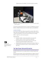
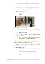
The recommended starting point for heat shoe air pressure is 50 PSI.
Turning the heat shoe adjuster clockwise increases the pressure.
3.
After the heat sealer reaches operating temperature, set the
controller parameters, if not already set.
4.
Press Start in the LCD.
5.
Advance the tape using the Manual Trig button in the LCD.
6.
Check the sealed tape for the desired sealed position.
7.
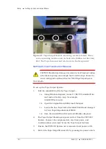
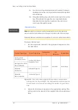
If necessary, adjust the inner seal position by turning the inner
seal adjuster (thumb wheel) clockwise (to move the seal away from
the operator) or counterclockwise. Tighten the position lock to
secure it.
8.
If necessary, adjust the outer seal position by turning the outer
seal adjuster (thumb wheel) clockwise to move the seal toward the
operator or counterclockwise (to move the seal away from the
operator). Lock the adjuster into place using the position lock
knob.
For Pressure Seal (PSA)
1.
To prepare the pressure seal. Set the temperature to Room
Temperature, 25
℃
.
2.
Advance the tape using Manual Trig button in the LCD.
3.
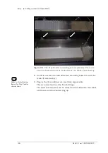
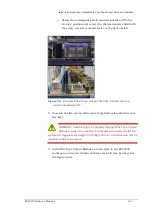
Adjust the inner and outer seal roller position. Align the roller
position over the strip of adhesive on either side of the PSA cover
tape. Both thumb screws have locking devices.
4.
Adjust the pressure at both sealer wheels to free spinning and then
1/8 revolution tighter. Use a 2 mm hex key.
5.
Advance the tape using the Manual Trig button in the LCD.
Re-adjust the seal roller pressure until the PSA adhesive is firmly
adhered to the carrier tape.
Note:
Excessive roller pressure may cause carrier tape advance problems
or elongation of sprocket holes in the carrier tape.
C
HECKS TO
P
ERFORM
P
RIOR TO
R
UNNING
6.
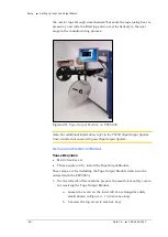
Mount an empty take-up reel on the spindle.
7.
Perform a Peel Force Test Perform as many peel force tests as
needed while adjusting the sealer controls to obtain the required
seal strength.
Summary of Contents for PSV5000
Page 12: ......
Page 36: ......
Page 160: ......
Page 161: ...Electrical Schematics for PSV5000 and Equipment ...
Page 162: ......
Page 163: ......
Page 164: ......
Page 165: ......
Page 166: ......
Page 167: ......
Page 168: ......
Page 169: ......
Page 170: ......
Page 171: ......
Page 172: ......
Page 173: ......
Page 174: ......
Page 175: ......
Page 176: ...PROGRAMMABLE MEDIA EXPERTS ...

