background image

DMS 80 / DMS 160 / DMS 240 / DMS 240 HSR 

www.dallmeier.com

52


¾

Mark the relevant periods by drawing a rectangle (

B

).


¾

Proceed analogous for all relevant periods / recording modes.


¾

Configure 

Exceptions

 if required.


¾

Confirm with 

OK

.


¾

Confirm the recording configuration dialog with 

OK

.

6.4.2 

Standard mode

In 

Standard

 track mode the images from a camera can be recorded in the LP track and 

in the S track. Thereby 

different recording modes

 may be used. The 

video quality set-

tings and the connection data are always valid

.

The following recording modes can be used with the various camera types in the 

Standard


track mode:

Analogue cameras

•  Permanent 
•  Motion
•  Contact

Dallmeier IP and HD cameras

•  Permanent 
•  Motion
•  Contact

Other IP cameras

•  Permanent 
•  Contact

6.4.2.1 

Permanent

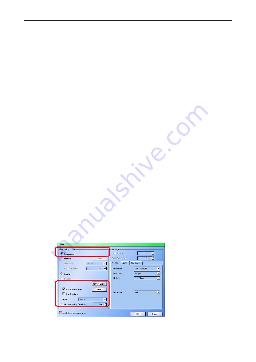
In the 

Permanent

 recording mode every image sent by the camera will be recorded.


¾

Set the 

Permanent

 recording mode.


¾

Observe the explanations given below.

Fig. 6-27 :  

Permanent

 recording mode

Summary of Contents for DMS 80

Page 1: ...English Rev 5 0 1 2010 06 22 Configuration and Data Hybrid audio and video recorder DMS 80 DMS 160 DMS 240 DMS 240 HSR ...

Page 2: ... or gross negligence of the manufacturer Dallmeier electronic GmbH Co KG Cranachweg 1 93051 Regensburg Germany www dallmeier com info dallmeier com All trademarks identified by are registered trademarks of Dallmeier electronic All trademarks identified by are trademarks or registered trademarks of the following owners Adobe and Flash of Adobe Systems Incorporated headquartered in San José Californ...

Page 3: ...ns 17 5 4 1 Alarm duration 18 5 4 2 Test modes 18 5 4 2 1 Compare 19 5 4 2 2 Performance 20 5 4 2 3 Tracking 20 5 4 3 Keyboard mode 21 5 4 4 Single split replay 21 5 4 5 Playback monitor 22 5 4 6 System messages 23 5 4 7 Assistant mode 24 5 4 8 Recording timeout 24 5 4 8 1 Max recording pause 25 5 4 8 2 Min Storage period 25 5 4 9 OSD texts 26 5 4 10 Logging 28 5 4 11 Recording monitor 29 5 4 12 S...

Page 4: ...nes 43 6 4 Recording mode 45 6 4 1 Manual and automatic mode 45 6 4 1 1 Permanent 46 6 4 1 2 Motion 47 6 4 1 3 Contact 48 6 4 1 4 Switching by motion 49 6 4 1 5 Switching by contact 50 6 4 1 6 Switching by timer 50 6 4 2 Standard mode 52 6 4 2 1 Permanent 52 6 4 2 2 Motion 53 6 4 2 3 Contact 54 6 4 2 4 Sensor 56 6 5 Video quality 56 6 5 1 Manual and automatic mode 56 6 5 1 1 Analogue cameras 56 6 ...

Page 5: ...y sequence 79 7 2 3 Display frame rate 79 7 2 4 OSD display 80 8 Network and PAS 81 8 1 Ethernet 81 8 1 1 Manual configuration 82 8 1 2 DHCP 82 8 2 PSTN Terminal Adapter 83 8 3 Alarm hosts 83 8 3 1 Selection and name 83 8 3 2 Connection 84 8 3 3 Alternative alarm host 85 8 3 4 Connection check 86 8 3 5 Messages 87 8 3 6 Timer 90 8 3 7 Activation 91 8 3 8 EBueS 91 8 4 Parameter backup 92 8 4 1 Expo...

Page 6: ...d position 119 12 10 3 2 Enter name for position 119 12 10 4 Configure camera 119 12 10 4 1 Functions 121 12 10 4 2 Close menu and save configuration 122 12 10 4 3 Save camera configuration for direct selection 122 12 10 5 Reset camera settings 123 12 10 6 End UTC camera configuration 123 13 Optional functions 124 13 1 Signal loop through 124 13 2 PRemote 124 14 HDD management 126 15 User manageme...

Page 7: ... 16 1 Activation 136 16 2 Update 136 17 System parameter 138 17 1 Default system parameters 138 17 2 Parameter export 138 17 3 Parameter import 139 18 HDD replacement 140 18 1 Conditions 140 18 2 Localization of the HDD 141 18 3 Replace the HDD 141 19 Technical data 144 ...

Page 8: ...he operator No special technical knowledge is required Operation The document entitled Operation contains detailed descriptions on how to operate the unit General information on the appropriate use and maintenance is also provided The target audience of this document is the operator of the unit No special technical knowl edge is required Configuration and data this document The document entitled C...

Page 9: ... indicates practices for preventing property damage incorrect con figurations or faulty operations Expressions in bold italics generally indicate a control element on the device switches or labels or on its user interface buttons menu entries Paragraphs in italics provide information on basic principles special features and efficient procedure as well as general recommendations ...

Page 10: ...esult in loss of warranty Modifications Do not make any modifications to the hardware or software that has not been tested and approved by Dallmeier Inappropriate modifications can cause malfunctions damages and data loss and can result in loss of warranty Documentation Carefully and completely read the documents included in delivery Always observe the contained instructions notes and warnings Con...

Page 11: ...nnect it from the power supply pull out the power plug Contact the sales partner responsible for your area Opening The housing of the unit may only be opened by qualified personnel for inspection mainte nance and repair Disposal Disconnect the unit from the power supply Remove all connected devices Return the unit to your respective sales partner ...

Page 12: ...elivery may differ depending on the ordered equipment or device variant The device s range of functions depends on the ordered equipment or device variant and may therefore not correspond with this document s content Certain functions and features may require an activation that is subject to costs 3 2 Transportation and packaging Store the original packaging for transportation at a later date Dall...

Page 13: ...connected to the recorder Switch on the VGA monitor the peripherals and the recorder The connected analogue cameras 1 4 are displayed after the start Fig 4 1 In the initial state it is possible to login without password The rights of the Administ rator group are valid Note that the definition of the passwords and of the network parameters is necessary for remote access Dallmeier PView or DMS WebCo...

Page 14: ...DMS 80 DMS 160 DMS 240 DMS 240 HSR www dallmeier com 14 The graphical operation and configuration interface will be displayed Fig 4 3 ...

Page 15: ...n the Language dialog using Setup System Language Fig 5 1 Language dialog Select a Language Confirm with OK 5 2 System time The system time be set or retrieved from an external time emitter time server or radio clock The Date format and the Time zone must be adopted in any case Open the Time dialog via Setup System System Time Fig 5 2 Set the time manually ...

Page 16: ...e external time server check box Enter the IP address of the time server Check the connection to the time server with Ping Finally confirm with OK The time of the external time server is taken over as system time after the restart of the recorder 5 2 3 Radio clock The recorder can retrieve the system time from an external radio clock The USB radio clock DFM 1 USB is available for all Dallmeier rec...

Page 17: ...r systems are closed ex factory and can not be opened Relevant ports are open to ensure full compatibility Relevant ports that are not required can be closed in the System Security dialog Open the System Security dialog via Setup System System Security Fig 5 3 System Security dialog Activate the required protocols ports Deactivate the not required protocols ports Confirm with OK 5 4 Options The ba...

Page 18: ... is ended either by triggering the opposite Contact IN function or after the elapse of the Alarm duration Set the Alarm duration if necessary Confirm with OK 5 4 2 Test modes The test modes are designed to check the recording performance of the recorder and the selected function for analog cameras Please note that the evaluation is only possible on the actual recorder not for example via DMS NetCo...

Page 19: ...og cameras that are configured for Picture com parison recording mode Fig 5 7 Example of test mode Compare without detection Please note that the numbering A of the cameras starts at 0 camera 1 0 camera 2 1 etc Fig 5 8 Example of test mode Compare with detection If a motion is detected the area of the motion is shown in four additional views and marked B In addition the number of detection motions...

Page 20: ...track the frame rate Fp 1s and bit rate BRate will be shown in the following two lines The last line contains the total frame rate FTot and bit rate BRTot for the recording 5 4 2 3 Tracking The Tracking setting ensures that the coordinates of a motion that is relevant for SmartFin der will be shown in the live picture in addition to being saved to the database Fig 5 10 Example Tracking test mode P...

Page 21: ...oard mode Please note that the serial interface must also be configured 5 4 4 Single split replay To replay a track in a single split the whole of the split size is not used by the smaller formats QCIF CIF DCIF 2CIF It is possible to enlarge the picture however using the Single split replay option Original format Maintain the resolution QCIF CIF DCIF 2CIF Always 4 CIF Scale the resolution to 4CIF ...

Page 22: ... the blank area of the control panel 5 4 5 Playback monitor At standard settings the recorded images will be displayed on the VGA monitor in playback mode The Monitor option allows to switch playback to on of the two CVBS monitors M1 or M2 Fig 5 14 In this case the VGA monitor will display a live image in playback mode But the panel for playback control displayed on the VGA monitor is used further...

Page 23: ...ges dialog Certain system messages can be indicated additionally with a warning dialog or warning tone Open the System Messages dialog via Setup System Options System Messa ges Fig 5 15 System Messages dialog Activate the required message categories Deactivate the not required message categories Finally confirm with OK Deactivated messages will be indicated nevertheless by the corresponding LED on...

Page 24: ...t Mode dialog will be displayed Fig 5 16 Dialog selection for assistant mode Activate Assistant Mode for the group s by checking the appropriate checkbox Define the relevant setup dialogs for the user group by checking the appropriate check box Finally confirm with OK Please note that a user group must by authorized to configure the relevant setup dialogs see User management 5 4 8 Recording timeou...

Page 25: ...b Set the Maximum recording pause for the relevant cameras tracks Confirm with OK 5 4 8 2 Min Storage period The Min Storage period is relevant for all recording modes A track recording can be defined to cover a certain period normally Various events can cause a situation when more images have to be recorded or more memory capacity is required Recording mode Event Motion More motion than expected ...

Page 26: ...boxes for 40 characters each can be defined using the OSD Text option These will be displayed in the live picture and will be saved with the picture Click on Set OSDText to open the OSD Text Configuration dialog Fig 5 19 OSD Text Configuration dialog Enter text To enter texts in boxes 1 8 click in section A The virtual keyboard will be displayed Enter the text Confirm with OK The text will be disp...

Page 27: ...ilable variables are displayed in the OSD Text Configuration dialog in the form of a table header tool tip Fig 5 20 Tool tip with the available variables Adjust position To adjust the position of text boxes 1 8 click in section B The current camera picture will be displayed The text boxes are positioned one on top of the other in the top left hand corner Fig 5 21 Positionierung OSD Text Move the r...

Page 28: ...ns parency to the camera picture Set an enlargement of the text box if required in Zoom horiz vert Finally confirm the OSD Text Configuration dialog with OK 5 4 10 Logging In addition to system messages the recorder also allows user actions to be logged The analysis of the log data is done in the System messages dialog as well Open the Configure logging dialog via Setup System Options Setup Loggin...

Page 29: ...eckbox Activate the Recording monitor option if required Finally confirm with OK 5 4 12 Simple Export The regular export function is activated in the recorder s default configuration The user has to select the relevant sequences images in the single tracks manually before the export The Simple Export option allows switching to a simplified export function The user only has to select one relevant i...

Page 30: ...Eject after export If this option is activated the export medium DVD CD will be ejected after the export is completed Note that this option is also valid for the regular export function 5 4 13 Audio deactivation This option relates to audio reproduction in the live mode In the recorder s default configuration the audio reproduction is deactivated when the ca mera is changed or a new split is selec...

Page 31: ... activated in the appropriate track recording buttons The recording is configured in the next columns C The size of the recording track LP track can then be defined under Storage Settings D Finally various recording options can be activated and configured in Other Settings E Note that the available recoding options and functions depend on the track mode and the type of camera analogue IP HD 6 1 Tr...

Page 32: ...ll tracks have to be deleted The video quality settings can be modified In this case normally the recordings in the corresponding track have to be deleted 6 1 1 3 Track types Longplay tracks LP tracks are generally large ring memories They are used for ongoing recording One LP track is available for each camera Secure tracks Secure tracks are generally relatively small ring memories One S track ca...

Page 33: ...d HD cameras Permanent Motion Contact Other IP cameras Permanent Contact 6 1 2 Manual In the manual track mode the entire video memory will be segmented into memory units automatically Every camera track is assigned a particular number of the memory units manually track size Thereby static tracks will be defined The size of the tracks can be modified anytime without the need to delete recordings F...

Page 34: ...a One reference track see above is available independent from the recording settings 6 1 2 4 Recording modes The following recording modes can be used with the various camera types in the manual track mode Analogue cameras Permanent Motion Contact Permanent with switching of recording mode quality by timer Permanent with quality switching by motion Permanent with quality switching by contact Dallm...

Page 35: ...The size of the tracks can not be modified manually It will be adopted automatically No recordings have to be deleted Tracks can be dropped and new tracks can be created without deleting other tracks or recordings The video quality settings can be modified anytime The recordings in the corresponding track do not have to be deleted 6 1 3 3 Track types One LP track see above is defined automatically...

Page 36: ...recordings have to be deleted NOTE When changing the track mode all recordings and various settings e g video quality camera timer have to be deleted Open the Recording Settings dialog via Setup Recording Camera Tracks Observe the explanations above Set the required Track Mode Fig 6 5 Setting Track Mode The Auto Configuration Options dialog will be displayed Fig 6 6 Default settings Observe the ex...

Page 37: ...ion to the cor responding video input In the Recording Settings dialog all connected analogue cameras will be labeled with a yellow symbol column Camera Name 6 2 2 IP cameras The connection to IP cameras is realized via a network Therefore the connection data IP address password has to be entered Right click in the Recording Settings dialog on the relevant recording button The IP Camera Setup dial...

Page 38: ... dialog the IP camera will be labeled with a yellow symbol column Camera Name Note that some of the camera s configuration dialogs e g encoder motion detection will be locked browser configuration as long as it is connected to an active recorder 6 2 2 2 Other IP cameras After corresponding selection and confirmation of the IP Camera Setup dialog the dialog for configuration of another IP camera wi...

Page 39: ...ression is provided in the documentation supplied with the camera Example Axis http xxx xxx xxx xxx jpg image jpg IQEye http xxx xxx xxx xxx now jpg snap post 6 3 Basic configuration The basic configuration normally is independent from the track mode the camera type and other settings Exceptions will be pointed out 6 3 1 Camera and track name In the Camera Name column all cameras are displayed as ...

Page 40: ... in default configuration the camera timer can be activated or deactivated in a camera s recording settings dia log Open the Camera Timer dialog via Setup Recording Camera Timer Fig 6 11 Camera timer dialog Select the relevant camera in the Cameras section Set Active and Inactive times as described in the following Set Exceptions as described in the following Proceed analogous for all relevant cam...

Page 41: ...a rectangle B Exceptions The Standard settings are valid for all 52 weeks of a year Exceptions can be defined for single days Select the Exception option Use the schedule C to select the relevant week Fig 6 13 Exceptions Set active and inactive periods D for the relevant day as described above The relevant day will be displayed in the Exceptions list Proceed analogous for all relevant days Confirm...

Page 42: ...up Recording Tracks Timer Fig 6 14 Tracks timer dialog Select all S tracks s or the relevant LP track in the Tracks section Set Active and Inactive periods as described above If necessary set Exceptions as described above Confirm with OK The Tracks Timer will be reset when the track mode is changed 6 3 4 Areas The Areas dialog enables the definition of active relevant image areas for motion detect...

Page 43: ...ve areas by drawing a rectangle Fig 6 16 Inactve areas Proceed analogous for all active and inactive areas Proceed analogous for all relevant cameras Confirm with OK 6 3 4 2 Private Zones In default configuration the entire image will be displayed and recorded Private zones can be defined if specific image areas should not be visible A black area will be displayed and recorded instead of these zon...

Page 44: ...drawing a rectangle Fig 6 18 Private Zones Adopt the zones if necessary Position ð Left click Drag Drop Size ð Left click on the border Drag Drop Delete ð Right click Proceed analogous for all private zones Proceed analogous for all relevant cameras Confirm with OK Private zones do not represent an overlay These image areas will not be saved Private zones can not be rebuilt ...

Page 45: ...ration dialogs Rightclick in the Recording Settings dialog on the relevant recording button The recording configuration dialog for the corresponding camera will be displayed Fig 6 19 Recording configuration 6 4 1 Manual and automatic mode The following recording modes can be used with the various camera types in the manual and automatic track modes Analogue cameras Permanent Motion Contact Permane...

Page 46: ...the default configuration it is possible to save certain information with the pictures in the track for example indices set using the Set marker on Camera Contact option When the Use Database option is activated this information additionally will be saved in a database The advantage of the database is demonstrated when playing back or searching within a large track A search for certain events is g...

Page 47: ...base option if required Configure the Active Areas if required see section Basic configuration Set the Sensitivity of the motion detection Set the Pre Event time and the Post Event time Set the Motion Estimation for the memory calculation Confirm with OK Sensitivity The more sensitive the image comparison is the less the proportion of the picture contents must change to trigger an image comparison...

Page 48: ...e the explanations given below Fig 6 22 Contact recording mode Configure Private Zones if required see section Basic configuration Activate configure the Camera Timer if required see section Basic configuration Activate the Use Database option if required Set the Pre Event time see above Set the Contact Recording Duration if required Set the Options for contact recording Confirm with OK Normal Sin...

Page 49: ...etween two consecutive images an image comparison event event has taken place This picture comparison event triggers the swit ching to permanent recording with high video quality Recording with high video quality will be stopped when the Switching Duration is expi red and no further motion is detected Ensure that the Expert Mode option is activated Set the Switching by motion recording mode Observ...

Page 50: ... is activated Set the Switching by contact recording mode Observe the explanations given below Fig 6 24 Switching by contact recording mode Configure Private Zones if required see section Basic configuration Activate configure the Camera Timer if required see section Basic configuration Activate the Use Database option if required see above Activate the Set marker on Camera Contact option if requi...

Page 51: ...tion Activate the Use Database option if required see above Set the parameters for the Motion recording mode A as described above Set the parameters for the Contact recording mode B as described above Proceed as follows in order to configure the switching Open the camera timer dialog with a click on Timer The extended Camera timer for camera x dialog will be displayed The definition of periods and...

Page 52: ...k and in the S track Thereby different recording modes may be used The video quality set tings and the connection data are always valid The following recording modes can be used with the various camera types in the Standard track mode Analogue cameras Permanent Motion Contact Dallmeier IP and HD cameras Permanent Motion Contact Other IP cameras Permanent Contact 6 4 2 1 Permanent In the Permanent ...

Page 53: ... case and cannot be unchecked Options Note that a contact input must be configured for the relevant camera see chapter Contact IN Save This option is available for S tracks only recording will be stopped when the contact has been triggered The S track will be locked If an empty S track is available recording will be continued in it Event The function of this option is the same as Save It will not ...

Page 54: ... with motion It affects only the estimated recording duration Estimate in the track Pre Event time This option enables you to set a period during which the latest images from the camera are retained in a buffer If an event occurs these images are saved together with the recording in the track This allows the situation prior to the event to the evaluated Post Event time The Post Event time specifie...

Page 55: ...act switching It continues until the contact is released again Start The recording is triggered by the contact switching The recording is stopped by an op posite contact function Stop recording Contact recording mode or Stop recording camera Contact recording mode Timer The recording is started by the contact switching Recording is stopped after the Contact Recording Duration expired Toggle The re...

Page 56: ...tions will be compensated by automatically adjusting of the values In some cases the track size has to be reduced or the number of available channels adjusted Right click in the Recording Settings dialog on the relevant recording button The recording configuration dialog for the corresponding camera will be displayed Proceed as described in the following 6 5 1 Manual and automatic mode Recording m...

Page 57: ...hus has a direct impact on the image quality of the recordings A low bit rate stands for a high degree of compression with a relatively small volume of data But the image quality also is poor A high bit rate stands for a low degree of compres sion with a relatively large volume of data The Image quality is very good Deinterlace This function can be activated to increase the picture quality It redu...

Page 58: ...es better use of the available hard disk space The variable setting changes the bit rate in accordance with the activity changes in the image You can limit the fluctuation of the bit rate by making the appropriate setting which is done as a percent Example With a set bit rate of 4 Mbps and a bit rate mode variable by 50 the bit rate can vary from 6 Mbps to 2 Mbps during recording Audio Bit Rate Th...

Page 59: ... the current version It can not be set separately 6 5 1 3 Other IP cameras Most IP cameras from other manufacturers use proprietary protocols protected by licen ses to transfer pictures It is therefore not usually possible to implement them to record the video stream The other feature that these cameras have in common however is that they supply single pictures in JPEG format on demand These can b...

Page 60: ... via the network can be en tered in this box This function is independent of the request for pictures HTTP request string 6 5 2 Standard mode In the Standard track mode the video quality settings are valid for recording in the LP track and in the s track 6 5 2 1 Analogue cameras Note that the settings on the Alarm and Pre Event tabs are not supported in this version Observe the explanations given ...

Page 61: ... the Frame Rate Set the Bit Rate Set the Bit Rate Mode Activate Deinterlace if required Set the Encoding Mode and GOP size if required and supported Confirm with OK 6 5 2 3 Other IP cameras Observe the explanations given above Fig 6 36 Other IP cameras Set the Frame Rate Set the Check Interval Confirm with OK ...

Page 62: ... OK In the Standard track mode these settings are valid for recording in the LP track and in the S track 6 5 3 2 Auto configuration After the track mode has been changed see above the Auto Configuration Options dialog will be displayed It can be used anytime in the Standard track mode and enables the uniform configuration of all cameras with default settings NOTE When using this function all recor...

Page 63: ...he B frame option if required Proceed analogous for all relevant cameras Finally confirm with OK B frames active The camera is sending the video stream with B frames Encoding on the camera and decoding on the recorder require more time min 120 ms This results in an addition delay But the video quality depending on the bit rate can be increased in some cases B frames inactive The camera is sending ...

Page 64: ...ar part of the entire video memory manually track size NOTE In the Standard track mode all recordings need to be deleted if the video memory configuration is modified 6 7 1 1 Longplay tracks The video memory for the single Longplay tracks is defined directly in the Recording Settings dialog This can be done with two variables HDD Share of the track from the entire video memory in percent Estimate ...

Page 65: ...tion if required Finally confirm with a click on S Tracks Number The Number of s tracks should be a multiple of the number of cameras that record to an S Track This is necessary because S tracks are disabled saved in certain situations In this case the recording can only be continued if a new S track is available Length This value sets the recording duration of the single secure tracks in seconds ...

Page 66: ... required memory capacity will be kept contend by dynamic adjustment of the resolution The period covered in the track will then remain constant Configure the video memory as described above Ensure that the Expert mode is activated Activate the Fixed recording duration option Fig 6 43 Confirm with OK 6 7 2 Manual In the manual track mode the entire video memory will be segmented into memory units ...

Page 67: ...e displayed value 6 8 Other functions The following functions are not available for all camera types If required the corresponding buttons are deactivated in the Recording settings dialogue 6 8 1 Audio When the Audio function is activated for a camera the signal of the corresponding audio channel also will be recorded Fig 6 46 Audio activation Activate the Audio function with the appropriate check...

Page 68: ...ent can trigger one are more actions Leftclick the relevant SEDOR button Fig 6 48 SEDOR activation First the button will be displayed red The image analysis starts automatically learning pha se and generates reference data When it is complete the button will be displayed green The SEDOR function is active for the corresponding camera Information on SEDOR status analysis and learning phase will be ...

Page 69: ...ghtness precipitation can cause false messages Fig 6 50 SEDOR sabotage configuration Select the Sabotage tab if required Observe the explanations given below Set the Limit for the acceptable deviance Set the Minimum learning phase Set the Minimum alarm delay Finally confirm with Close Limit The Limit is the acceptable deviance between current image and reference data If the Limit is set very low a...

Page 70: ...term sabotage actions can not be detected SEDOR SmartFinder Advance The SEDOR SmartFinder Advance module detects static objects that have been added or removed from a scene A detected object event is saved with the corresponding coor dinates in a data base Evaluation of the object events can be done for arbitrary image sections with the external Dallmeier software PView Note that the function is n...

Page 71: ...ered However short term added or removed objects can not be detected 6 8 4 SmartFinder The SmartFinder function detects motions by analyzing and comparing subsequent ima ges A detected motion event is saved with the corresponding coordinates in a data base Evaluation of the motion events can be done for arbitrary image sections with the external Dallmeier software PView or with the recorder s GUI ...

Page 72: ...ew false messages can be anticipated Decay time The Decay time determines how long a motion event is valid If an additional motion event is detected in the same image section before this period expired it will not be rated as a new event This setting allows to reduce events that are caused by repeated motions of the same object Validity period This option is not integrated in the current version 6...

Page 73: ...n the Recording Settings sub dialog Fig 6 54 Camera control activation Right click on the relevant control button The Recording Settings sub dialog will be displayed The available connection types depend on the serial interface settings Fig 6 55 Connection setting Select the relevant connection to the camera Complete the camera control configuration as described in the section Optional periphery ...

Page 74: ...dialog via Recording Camera Descriptions Fig 7 1 Camera Descriptions dialog Enter the description text for the Recorder Enter the description text for the relevant Cameras Confirm with OK The display of the description texts during playback must be activated separately Open the Search Items dialog via Recording Search Items Fig 7 2 Search Items dialog Activate the search item Recorder description ...

Page 75: ...up System Display Splitter Fig 7 3 Dialog Splitter All the available cameras will be displayed by a yellow button in the Cameras box Select the cameras for which the settings are to be made Define whether you wish to configure a Live Split sequencer live mode or a Playback Split playback live mode and playback mode Select a Split Type The various splits may be preset camera number depending on the...

Page 76: ...t type in order Auto all results in the automatic assignment for all split types of the currently selected combination of Monitor and split type live or playback split 7 1 2 Manual assignment Fig 7 5 Manual assignment First click on a split to mark it Click on one of the available camera buttons to make an assignment The marked split will not be assigned a camera if you click on Empty Split ...

Page 77: ... displayed in the live mode single split only Open the Sequencer dialog using Setup System Display Sequencer 7 2 1 VGA display sequence The display sequences for the various monitors must be defined on separate tabs All the available cameras will always be displayed by a yellow button in the Cameras box Fig 7 6 Sequencer VGA dialog Click on the Cameras buttons in the required order to add them to ...

Page 78: ...again Event switching An interruption to the current sequencer can be defined by checking the Event Switching checkboxes Fig 7 8 Define event switching Movement An arbitrary camera can be defined to record using the Motion Detection recording mode If a movement is detected start recording the live picture from this camera will be dis played for 5 seconds After this the sequencer will continue auto...

Page 79: ...as Display Sequence and Event Switching boxes will be disabled Any set tings that you have already made will be ignored 7 2 3 Display frame rate The frame rate can be adjusted for every monitor in the lower area of the Sequencer dia log This frame rate reduction of the playback output will help to decrease the system load Fig 7 10 In effect there will be more performance available for the recordin...

Page 80: ...itor 6 fps CVBS Monitor 1 6 fps CVBS Monitor 2 25 fps After breaking the connection the original settings will be restored again 7 2 4 OSD display The OSD function can blend in the camera name and the current time in the image dis played on a CVBS monitor Select the relevant CVBS monitor tab Fig 7 11 Set the camera name or the camera description as Name Set the format for the Time Confirm with OK ...

Page 81: ...ork dialogue the bit rate off all IP cameras recordings is reduced when many IP cameras are used with a too low network speed e g 10 Mbps the default settings are used Use DHCP inactiv Allow IP Finder configuration activ FQDN SSL Certifikate inactiv IP Adress 192 168 2 230 Subnet mask 255 255 255 0 Data rate Auto Host name system Domain name dallmeier com Open the Ethernet Tokenring dialog via Set...

Page 82: ...ork settings must be assigned manually if no DHCP Server is available Observe the designated and valid IP address ranges of the network Ensure that the DHCP checkbox is deactivated Enter the IP address Enter the Network mask Enter the Gateway address Set the Data rate if required Enter the Host name system name if required Enter the Domain name if required Deactivate the Allow IP Finder network co...

Page 83: ...nfiguration connection type message type and activation period of up to 8 addressees is made in the Alarm Hosts dialog Open the Alarm Hosts dialog via Setup Network Alarm Hosts Fig 8 2 The 8 alarm host will be displayed in a select list They have to be configured as described below before their activation Apply saves the current setting without the need to confirm and close the dialog with OK 8 3 ...

Page 84: ...s Name for alarm host Close the virtual keyboard with OK 8 3 2 Connection The specification of the connection type and the entry of the address data are made in the Connection type section Take into account that the current recorder version supports message transmission via the Ethernet interface only Select an alarm host with a left click in the alarm host list Select the transmission type Ethern...

Page 85: ...g 8 5 Please not the GUI s explanations Please not the explanations below If necessary make the required changes Confirm with OK If options A or C have been selected the connection attempt will be tried until it actually is successful and the message can be send to the alarm host If option B is selected the connection attempt will only be tried X times Then the message will be discarded or send to...

Page 86: ... successful transmission can be controlled at the alarm host PGuard The recorder does not receive an acknowledgement Select an alarm host with a left click in the alarm host list Open the Alarm Host check configuration dialog with Alarm Host check Fig 8 8 There are three options to set the transmission time 1 Activate the Interval radio button in order to send the test message in defined time in t...

Page 87: ...low Confirm with OK Alarm This message will be send if the recorder starts or ends its alarm state The alarm state is triggered by the Start alarm contact IN function It is stopped by the corresponding contact IN functions or after the set alarm duration System Options Alarm duration being expired Event This message will be send if the recorder starts recording of an arbitrary camera because of a ...

Page 88: ... rotate anymore The front fan rotates again The revolution of the rear fan cannot be determined Error during determination of the revolution of the rear fan The revolution of the rear fan can be determined The rear fan does not rotate anymore The rear fan rotates again The revolution of the HDD fan cannot be determined Error during determination of the revolution of the HDD fan The revolution of t...

Page 89: ...f a contact IN function Start recording camera recording mode Contact No Recording This message will be send if no recording is triggered in a particular track in a defined period Relevant are cameras tracks with the recording mode motion or contact The appropriate configuration is done in System Options Recording Timeouts SEDOR Alarm Sabotage This message will be send if SEDOR detects a sabotage ...

Page 90: ...uninterruptible power supply unit UPS sends a message that is forwarded to the alarm host 8 3 6 Timer After its activation see in the following the messages will be sent to the alarm host anytime 24 7 Differing from this standard configuration it is possible to limit the host s active time Select an alarm host with a left click in the alarm host list Activate the host timer with the Timer active c...

Page 91: ...een a recorder and an alarm host The recorder can send all messages concerning states and events see chapter Alarm hosts Messages Which messages actually will be processed and displayed by EBueS depends on the EBueS server configuration In order to avoid needless network traffic only relevant messages should be sent The EBueS will only be displayed when the appropriate function has been activated ...

Page 92: ...tory if necessary Check the settings by sending a test message Confirm with OK The EBueS alarm host can be configured subsequently as described above 8 4 Parameter backup The network parameter can be saved on an external medium for backup or editing 8 4 1 Export The files saved during the export of the network parameter contain system name see above alarm hosts Ethernet PSTN and where applicable t...

Page 93: ...Import Export Export Fig 8 14 Select the relevant medium as Target Confirm with OK 8 4 2 Import Files that have been saved or edited on a PC can be integrated via Import again Open the Import network files dialog via Setup Network Import Export Import Fig 8 15 Select the relevant medium as Source Confirm with OK ...

Page 94: ...e functions of the interface depend on various software and hardware options The scope of functions depends on the ordered version not on the content of the documentation None The interface is deactivated Commanding This function allows the recorder to be controlled by an external application device via the serial interface DaVid protocol Control commands are only received however no confirmation ...

Page 95: ...irection confirmation signals from the camera are read at the serial port and sent via LAN to PView DNI external system This setting allows an external system to be connected for example an automatic teller ma chine ATM access control system or a Huth cash desk via a Dallmeier Network Interface DNI 1 UPS This function allows communication with an uninterruptible power supply unit UPS This means th...

Page 96: ...ng of the relevant camera is started if the required recording settings have been made If you do not wish to record a camera using the Contact recording mode the function can be changed in the same way as the global contacts 10 2 Make and break contact functions First of all only the configuration of the Make contact function function n o of the con tact inputs will be displayed The functions that...

Page 97: ...e Function n c These are executed in order when the contact is switched or released Fig 10 3 Select function Left click into the line of the relevant Function A Select a function from the drop down box B Contact parameters also have to be declared for some functions This is indicated by dis playing an orange button next to the function name Click on Contact parameters button C The Contact Paramete...

Page 98: ...ks Extend alarm The recorder is in alarm state If the Extend alarm contact function is triggered before the end of the alarm duration the alarm state will be extended indefinitely or until the corres ponding track is full The alarm state can then only be stopped by the Stop alarm contact function Delete alarm The last alarm state will be canceled Saved secure tracks will be deleted Locked tracks w...

Page 99: ... is defined in the Contact Parameter dialog Start Camera This function starts the recording of one camera that is defined with recording mode Contact Which camera is relevant is defined in the Contact Parameter dialog Stop Camera This function stops the recording that is still active timer can be expired that was triggered by Start recording Camera recording mode Contact Which camera is relevant i...

Page 100: ...Quality Which camera is relevant is defined in the Contact Parameter dialog Every activated camera can be selected It does not matter if the camera is connected or configured for recording Reset Recording Quality This function is relevant for cameras with the recording mode Switching by contact It switches the recording quality to Normal Quality Which camera is relevant is defined in the Contact P...

Page 101: ...ns The available functions of the interface depend on various software and hardware options The scope of functions depends on the ordered version not on the content of the docu mentation None No function selected Recorder in alarm select This function switches and holds the relay when the recorder is in alarm state The alarm state is triggered by the Start alarm contact IN function It is stopped b...

Page 102: ...The definition of a track as permanent storage and of the corresponding percent value is done by changing internal parameters Please contact the Dallmeier support team if necessary This function switches the relay if more than X of the reserved disk space of a track per manent storage are occupied The relay is held until the track is deleted The time for which the relay is held can also be set via...

Page 103: ... relay is held must be set via the Timer Housekeeping sabotage event The relay is switched if the system monitoring housekeeping detects an event of the ca tegory sabotage Events of the category sabotage are The BNC terminal has been removed The BNC terminal is ready for operation The relay is held until the system monitoring defines the status as normal The time for which the relay is held can al...

Page 104: ...nnot be determined Error during determination of the revolution of the front fan The revolution of the front fan can be determined The front fan does not rotate anymore The front fan rotates again The revolution of the rear fan cannot be determined Error during determination of the revolution of the rear fan The revolution of the rear fan can be determined The rear fan does not rotate anymore The ...

Page 105: ...printer may also be used 12 1 1 Create printer Open the Printer dialog via Setup Interfaces Printer to configure the printer Fig 12 1 Printer dialog Click on New to create a new printer The New Printer dialog will be displayed Fig 12 2 New Printer dialog The recorder basically supports all displayed printer manufacturers The printer must meet the following requirement in order to print the recorde...

Page 106: ...ticular printer Select the Manufacturer of a suitable printer Select a suitable Model Enter the Printer Name Confirm with OK The new printer is listed in the Printer dialog with the name you have entered for it In ad dition the default Properties will be displayed Fig 12 3 Printer dialog with created printer The device marked in the Printer box can be deleted by clicking on the appropriate Delete ...

Page 107: ...he Queue raw If necessary contact your network administrator Select the required Resolution Set the picture quality using the Brightness Contrast Hue and Saturation controls Confirm by clicking on OK The Printer dialog will appear again End the configuration of the printer by clicking on OK After ending the configuration clicking on OK in the Printer dialog a test page will be printed automaticall...

Page 108: ...s for the connection and configuration of the DAS 303 and DAS 4 Eco are provided in the corresponding documentations 12 4 Weather server The recorder can receive climatic data from a sensor or the MessPC Ethernet Box wea ther service through a network connection Open the Weather Sensor configuration dialog via Setup Interfaces Weather Server to configure the connection and request the data Fig 12 ...

Page 109: ...ine access control system or cash desk system can be connected to the recorder via a DNI This allows the data from the external system for example sort code time that a door was opened or amount of a cash desk transaction can be displayed in the live picture and saved with that picture Interface After connecting the DNI the serial interface must be configured accordingly Open the Serial Interfaces...

Page 110: ...ect the required Protocol Configure the DNI by clicking on Program Confirm with OK A precise description of the procedure is set out in the appropriate DNI documentation 12 5 2 DNI camera control A controllable camera dome PTZ camera can be connected to the recorder via a DNI This allows the dome or tilt and turn head of a camera to be controlled using the recorder s control interface Interface Af...

Page 111: ...camera control as the function Confirm with OK Protocol The next step is to configure the DNI itself Open the Camera Control dialog via Setup Interfaces Camera control Fig 12 10 Camera Control dialog First open the data for the DNI Network by clicking on Read Mark the relevant DNI Select the required Protocol Configure the DNI by clicking on Program Confirm with OK ...

Page 112: ...scription of the procedure is set out in the appropriate DNI documentation 12 6 UPS The use of a UPS uninterruptible power supply allows the recorder to be operated without problems even in the case of temporary power cuts In addition the recorder can receive and display the status messages from a UPS connected via a USB port of the serial interface NOTICE Potential malfunction of the UPS Use only...

Page 113: ... the recorder software 12 8 VSC A Dallmeier VSC 1 Video System controller control station for dome PTZ cameras can be connected to the recorder Selection and control of the camera is done on the control station displaying of the images on a recorder s monitor The Video System Controller dialog allows the specification of the monitor and the split type that will be used These settings are valid in ...

Page 114: ...e relevant user group has to be activated separately in the User Management 12 9 Serial PTZ cameras Suitable Dallmeier dome cameras DCCP protocol can be connected and controlled via the RS485 serial interface Note the documentation Commission of the recorder documentation Operation of the recorder documentation Installation and Configuration of the camera Connect the dome camera as described Commi...

Page 115: ...K The allocation of the control to the relevant cameras is made in the Recording Settings dialogue Open the Recording Settings dialogue via Setup Recording Cameras Tracks Left click the relevant control button Fig 12 15 Select the relevant interface if required The control function is activated for the corresponding camera The setting of the con nection type is made in the Recording Settings sub d...

Page 116: ...can be configured via the recorder s user interface No special cabling is required for this purpose The data are transferred using the coaxial cable UTC Up the Coax used to transfer picture data The UTC function requires a direct connection of the camera and recorder If a video distributor or amplifier is used between the camera and recorder the UTC function cannot be used 12 10 1 Required setting...

Page 117: ...bol for a dome camera will first be displayed in the Control column In this case right click on the symbol The Recording settings camera control dialog will appear Fig 12 20 Recording settings dialog camera control Click on UTC Camera Instead of the symbol for a dome camera the symbol for a normal camera will be displayed in the Recording settings dialog Fig 12 21 Camera symbol box Finally confirm...

Page 118: ...et settings 12 10 3 Zoom function By clicking on Zoom in 1 you can reduce a picture section in 11 stages in digital form Clicking on Zoom out 2 increases the size of the picture section The position of the section in the full picture is displayed in the preview window with a border If the mouse pointer is inside the rectangle you can position the zoom area B whilst holding the mouse button Fig 12 ...

Page 119: ...ns with the mouse pointer and right click on it Select Save Position Fig 12 24 12 10 3 2 Enter name for position Right click again on the button under which you have saved the position Select Change Name You can fix up to eight picture sections for each camera Fig 12 25 By clicking on one of the buttons you can select the appropriate section directly 12 10 4 Configure camera If you wish to adjust ...

Page 120: ...om 120 Fig 12 26 The camera menu is display in the picture and the relevant control elements are activated in the control panel Fig 12 27 Please see the precise description of the camera configuration in the documentation for the appropriate camera A B ...

Page 121: ...S 160 DMS 240 DMS 240 HSR www dallmeier com 121 12 10 4 1 Functions Select menu points Select settings Select save settings Back to preview menu Reset settings to default Direct selection of individual settings ...

Page 122: ...been restarted If you select Yes the settings will be saved and will still be valid even after the camera has been restarted 12 10 4 3 Save camera configuration for direct selection You can save individual settings for opening directly using buttons 1 to 3 Fig 12 29 Configure the camera to suit you wishes Close the camera menu using the Save settings option Go to one of the three selection buttons...

Page 123: ... Select Change name Enter your designation in the Change name dialog Click OK If you move the mouse pointer the relevant button the tool tip will be displayed with the new designation Fig 12 33 12 10 5 Reset camera settings All the individual settings can be reset and the camera can be returned to its factory con figuration NOTE If you reset the camera configuration all your individual settings in...

Page 124: ...ation Fig 13 1 Camera Termination dialog Set the termination of the relevant video input to OFF Confirm with OK 13 2 PRemote Normally the picture and audio will be transferred via the LAN or WAN in recording format H 264 However this can result in errors during playback caused by an external application for example in PView if the available bandwidth is too low In this case the external applicatio...

Page 125: ...240 HSR www dallmeier com 125 Open the PRemote Settings dialog via Setup Interfaces PRemote Fig 13 2 PRemote settings dialog Define the source of the Audio signal if necessary Enter the maximum available bandwidth Confirm with OK ...

Page 126: ...y by category bus system in a structure tree The total capacity available for recording is shown at the top right To enable or disable a hard disk drive for recording check or uncheck the checkbox in the Rec column RAID systems RAID Systems activate an additional dropdown box in the upper part of the dialog Fig 14 2 Selection RAID It is possible to deactivate RAID The various HDD s must be activat...

Page 127: ...onfiguration select one of the options offered Confirm with OK NOTE If any changes are made to the RAID settings all recordings must be de leted The Standard button can reset all RAID settings All HDD s that are currently connected will again be available for configuration ...

Page 128: ...ed access It is imperative that you define the group passwords Login as user can be activated using an enabling routine In this case individual users are assigned to the various groups with the rights of the group being granted to all the relevant users The login takes place using the user s name and password 15 1 Edit groups Click on Setup System User Management Fig 15 1 In principle rights may o...

Page 129: ... of the administrator group Fig 15 2 Select a group The authorizations in this group are displayed on the right in the form of a structure tree They can now be activated or deactivated by clicking on the appropriate checkbox Confirm by clicking on OK 15 1 2 Change group name or login Fig 15 3 Select a group Click on Edit group Enter the group name Login Click OK ...

Page 130: ...ord a second time for confirmation Click OK 15 1 4 Dual control login If access to a group is only possible by entering two passwords you can assign a second password to every group apart from the administrator which will then also be requested during the login procedure Fig 15 5 Select a group Click on Edit group Check the Dual control login checkbox Enter 2nd password ...

Page 131: ...ually Groups and assigned users can not evaluate images that are older than the set period in this case Fig 15 6 Activate the Restriction of track access option Set the permitted Max track access in hours and minutes Finally confirm with OK 15 2 Login as User After it has been enabled you can activate Login as User using the appropriate radio button Even if Login as User is active the group passwo...

Page 132: ...ck on the group to which a new user is to be assigned Click on Add User Fig 15 8 Enter a name for the new user in the Add User dialog Enter a New password Confirm password Click OK 15 2 2 User rights Users always have the same rights as the group to which they belong Proceed as descri bed in the chapter entitled Access rights to activate or deactivate the rights of a group ...

Page 133: ... can assign the current user a new password It is not possible to change the User login Fig 15 10 Enter Old password Enter a New password Confirm New password Click OK 15 2 4 Delete users If you wish to remove a user from a group mark the appropriate user in the user manage ment and then click on Delete User Two users must always be left in the Administrator group ...

Page 134: ...em User management The settings made in the Options dialog will apply to all groups and their users Fig 15 11 Mark the Login as user radio button The Options button will be activated Click on Options The User management Options dialog now enables you to make several settings for the login Fig 15 12 One user login Two user login Single admin user login Request strict password ...

Page 135: ...o log into the system Single admin user login If you also check the Single admin user login checkbox every user in the Administrator group will be given the right to log into the recorder individually using his own user login even if Two users login is set Request strict password If you wish to provide individual users with more secure passwords check the Request strict password checkbox If you cr...

Page 136: ...ystem These properties and functions can generally also be activated retrospectively It may be necessary to purchase some additional hardware together with an activation code for this purpose To enter the activation code open the Activation dialog via Setup System Service Activation Fig 16 1 Enter the activation code Confirm by clicking on OK Check the activated function 16 2 Update NOTE Disconnec...

Page 137: ... Update dialog via Setup System Service Software Update Fig 16 2 Load Update file Select the data Source where the update is located Click Load to load the files Mark the Update File Confirm by clicking on OK Follow the instructions show in the dialogs that are then displayed ...

Page 138: ...y settings open the Default System Parameters dialog via Setup System System Parameter Default Fig 17 1 Default System Parameters dialog Mark Default Confirm by clicking on OK NOTE When the recorder has been reset to factory settings all recordings video and audio and recording settings will be lost 17 2 Parameter export To adapt the system parameters for a specific customer or to archive system s...

Page 139: ...ll be saved in addition to the parameter files This contains various log and protocol files which permit the Dallmeier Support team to analyze the recorder if necessary 17 3 Parameter import System parameters that have been changed on a PC can be read back into the recording system and updated using the Import function Fig 17 3 Click Import Select the storage medium from which you wish to read the...

Page 140: ...interchangeable drawer units on the recorder are not hot pluggable or hot swappable The recorder must therefore be switched off before an HDD drawer unit can be changed Tested and approved hard disk drives Use only hard disk drives that have been tested and approved by Dallmeier to replace a defective or failed HDD HDDs that have not been tested and approved may cause malfunctions and may even cau...

Page 141: ...dditional hard disk drives will also be displayed 18 3 Replace the HDD NOTE Risk of data loss and or damage to the hard disk drive Ensure that both the recorder and the DAS 4 Eco have been switched off before you replace the HDD drawer unit NOTE Damage to components at risk from electrostatic discharge caused by tou ching them Ensure that you are electrostatically discharged earthed before you tou...

Page 142: ...rawer unit out carefully Fig 18 3 Remove the HDD drawer unit Undo the 4 screws on the underside of the HDD drawer unit Fig 18 4 Screws loosen Remove the defective HDD Secure the HDD drawer unit to the new HDD Use only the original screws supplied Ensure that the HDD and HDD drawer unit are flush at the rear ...

Page 143: ...to the housing Ensure that you slide it straight Do not use any force Fig 18 7 Lock the HDD drawer unit The front cover on the HDD drawer unit must be flush with the edge of the housing Reconnect the mains plug Start the recorder If you have satisfied all the conditions the HDD will be initialized when the recorder is star ted After this it will be ready for use and the recording process will cont...

Page 144: ... Layer 2 Operating mode PentaplexPlus recording streaming live viewing playback remote access Split display 1 4 9 13 16 25 IP cameras only via PView Recording resolution 4CIF DCIF 2CIF CIF QCIF analogue D1 4CIF Half D1 2CIF CIF QCIF IP Recording mode Permanent motion contact timer variable recording mode VRM Bit rate Per analogue channel DMS 80 160 Up to 3 fps at 4CIF Up to 5 fps at 2CIF Up to 12 ...

Page 145: ... 80 8x D SuB DMS 160 16x D SuB DMS 240 240 HSR 24x D SuB Ethernet 1x RJ45 10 100 1000 Mbps Ethernet Protocols Unicast IPv4 TCP HTTP IGMP DHCP ARP NTP UDP Contact IN DMS 80 14x each 4 functions DMS 160 22x each 4 functions DMS 240 HSR 30x each 4 functions Relay OUT 5x configurable as NO or NC Serial parallel USB PS 2 2x RS232 1x RS485 optional 1x IEEE 1284 3x USB 2 0 Mouse Keyboard Further Specific...

Page 146: ...it Contact IN The following specifications apply to all contact inputs Interfering pulses 10 ms are filtered out Contact input must be 1 V for low level at 1 mA VdS calms a contact duration of min 200 ms for alarm systems Relay OUT The following specifications apply to the relay outputs All relay outputs are floating contacts Switching speed at 200 ms VdS installations at 20 MS Voltage limits are ...

Page 147: ...ompany is responsible for this declaration Dallmeier electronic GmbH Co KG Cranachweg 1 D 93051 Regensburg The measurements were carried out in accredited laboratories For the evaluation of above mentioned Council Directives for Electromagnetic Compatibility and for Low Voltage following standards were consulted DIN EN 55022 1998 04 Class B DIN EN 50130 4 2003 09 DIN EN 61000 4 2 2001 12 DIN EN 61...

Reviews: