background image

Summary of Contents for PDR16-PC

Page 1: ......

Page 2: ...User s Manual ii ...

Page 3: ...TO PROVIDE REASONABLE PROTECTION AGAINST HARMFUL INTERFERENCE WHEN THE EQUIPMENT IS OPERATED IN A COMMERCIAL ENVIRONMENT THIS EQUIPMENT GENERATES USES AND CAN RADIATE RADIO FREQUENCY ENERGY AND IF NOT INSTALLED AND USED IN ACCORDANCE WITH THE INSTRUCTION MANUAL MAY CAUSE HARMFUL INTERFERENCE TO RADIO COMMUNICATIONS OPERATION OF THIS EQUIPMENT IN A RESIDENTIAL AREA IS LIKELY TO CAUSE HARMFUL INTERF...

Page 4: ...able system This will prevent damage to the equipment due to lightning and power line surges 11 Overloading Do not overload wall outlets and extension cords as this can result in the risk of fire or electric shock 12 Objects and Liquids Never push objects of any kind through openings of this equipment as they may touch dangerous voltage points or short out parts that could result in a fire or elec...

Page 5: ...2 SmartBackup 37 SmartPager 40 Chapter 3 Remote Access 47 Installation 47 POST System Setup 47 BASE System Setup 48 Appendix 1 Accessing Windows 55 Appendix 2 SmartShell 56 Appendix 3 Network Setup LAN 58 Appendix 4 Network Setup Modem 59 Appendix 5 WebGuard 81 Appendix 6 Protocol for Remote Controlling DVR 83 Appendix 7 Alarm Input Ouput Board 86 Appendix 8 Time Synchronization 87 Appendix 9 Trou...

Page 6: ...User s Manual vi ...

Page 7: ...ch camera input using graphic user interface Various image enhancement functions including zoom in out brightness interpolation blur and sharpness Remote monitoring playback and control through LAN PSTN and ISDN User friendly interface Proprietary encryption scheme preventing video from alteration 16 channel alarm input and 1 channel alarm output NOTE See Appendix 10 Specifications for the system ...

Page 8: ...r button in the SmartGuard mode or press the power button on the front panel to turn the system off NOTE When turning off the system you must confirm that you want to turn off the unit You will also be asked for a user ID and password or system quit procedure if the Shut Down option was selected for the user s authorization during SmartGuard setup CAUTION The system can be shut down by force by pr...

Page 9: ...urn on the system it will immediately begin recording If you have less than 16 cameras you must enter the setup screen and deactivate any inputs to which cameras are not connected otherwise the recording speed might be decreased somewhat Features 16 channels Max 120 images sec recording 100 images sec PAL User friendly interface Scheduling by camera and time Time lapse or event driven recording Mo...

Page 10: ...ce a check in the Show OSD box to display the OSD information Clock Mode Click the left mouse button on the clock area to set date display MM DD YYYY and time display 12 Hours 24 Hours formats Click the right mouse button on the clock area to set date time and time zone CAUTION If you change the time images dated later than the new date time are deleted Back up the images if you want to save them ...

Page 11: ...ges when the hard disk is full Event Logging To scroll up and down the list hold down the left mouse button on the list and move the cursor up and down or roll the mouse wheel on the list Image Adjust You can adjust the brightness contrast hue and saturation by clicking the designated buttons Click the Default button to reset them to the default settings NOTE These adjustments should not be used t...

Page 12: ...ate alarm output manually by clicking the button while it is released or deactivate an alarm output by clicking the button when it is pressed Setup When this button is clicked a dialog box appears The dialog box has nine tabs See the following SmartGuard Setup section Auto Sequencing When this button is clicked the SmartGuard sequences the cameras in order Whenever you click the button it toggles ...

Page 13: ...oard attached to your unit enter a location name such as Main Office If you do not have a keyboard connected to the unit clicking the keyboard icon will display a virtual keyboard on which you can type by clicking the letters 4 Move to Spot sequence dwell and set the sequence dwell time for the Spot monitor by holding down and dragging the pointer You can set the dwell time from 1 to 10 seconds If...

Page 14: ...hedule mode An S indicates it is in the Event driven recording mode An RS indicates it is in the Time Event recording mode An R located at the bottom right corner indicates the DVR is recording video and the blink rate of the R relates to the recording speed 15 Move to Remote control and check the box when the DVR is controlled remotely using RS232C or RS485 communications signals See Appendix 6 P...

Page 15: ...t select the Stop bit from 1 bit or 2 bits from the drop down list Move to Device ID and set the device ID number from 0 to 127 using the slide bar You can save your changes by clicking the OK button Selecting Cancel exits the dialog box without saving the changes 5 Move to Hide image and check the box to hide the image of the selected camera on the monitor If this box is checked the selected came...

Page 16: ... and set the duration from 1 second to 1 minute of pre alarm recording by holding down and dragging the pointer 16 Move to Rec image resolution and set the record image size recorded by holding down and dragging the pointer You can select the resolution from 160x120 320x240 640x240 or 640x480 NOTE Higher resolution images require more storage space and will reduce the recording capacity of the har...

Page 17: ...3 Move to On Priority alarm and check the box if you want to use an advanced setup during high priority alarm activation Then set the Recording speed Rec image resolution and Rec image quality by holding down and dragging the pointer Refer to the steps 10 to 17 for the available values for each setting 24 You can save your changes by clicking the OK button Selecting Cancel exits the Advanced camer...

Page 18: ...on in the same dialog box and then click the Paste button 5 Click the Apply all button if you want to adjust the current settings to all cameras 6 Click the Set up holiday button to set up holidays This function compensates for different holidays in different countries 7 Click the date in the calendar you want as a holiday and click the Add button The selected date will be displayed in the list ne...

Page 19: ...th the sensor and the DVR is recording video 8 Click the Set up Audio button Select an audio input type from Microphone or Line in and set its balance and volume in the Recording Control dialog box NOTE The sound card provides two types of audio input Microphone and Line in Microphone is for an unamplified source while Line in is for an amplified source You must manually select the type of input N...

Page 20: ...ed zone established in step 8 5 Move to High priority and check the box to give high priority to the target camera The DVR will follow the advanced camera setup when the target camera detects motion See the Setting Up Cameras for configuring advanced camera setup 6 Move to Record Audio and check the box to record audio when a selected camera detects motion Recording audio will be activated when th...

Page 21: ...ppears Once the rectangle is the size you want release the mouse button and the rectangle fills with boxes Fill When using the fill tool clicking the mouse will fill that area of the image with boxes If a shape has been drawn with the line tool clicking inside will fill the area with boxes Clicking outside the area will fill the outer area with boxes If no shapes have been drawn the entire screen ...

Page 22: ...low the advanced camera setup when the target camera detects motion See the Setting Up Cameras for configuring advanced camera setup 5 Move to Camera association and click the camera icon to associate it with the camera selected step 1 If video loss is detected by one camera other cameras can be associated with it so that video will also be recorded from the associated cameras 6 Move to Alarm asso...

Page 23: ...the box to enable the selected alarm 3 Move to From and set the beginning time 00 00 to 24 00 of alarm activation by holding down and dragging the pointer 4 Move to To and set the ending time 00 00 to 24 00 of alarm activation by holding down and dragging the pointer NOTE In cases where the From hour is later than the To hour the alarm will be activated at the From time of the current date until n...

Page 24: ...he lower the value the more images are transferred during the same time For example when using one camera the value 30 means one image per 30 seconds will be transmitted 1 means one image per second and 1 30 means that 30 images per second The maximum transmit speed users can expect over a LAN is 120 images per second This means that if you have four cameras they can all be set at 1 30 30 images p...

Page 25: ...r details 11 Move to Center and enter the IP address of each server A maximum of three servers can be set NOTE When selecting the Use Modem enter the telephone number of the target sever instead of the IP address 12 Move to Retry Counts and enter the number of times you would like to DVR try contacting the server if the connection fails 13 Move to When and select the target event The DVR will call...

Page 26: ...sing either the actual keyboard or the virtual keyboard 3 Move to Authority level and select the authority level from a drop down list User Group 1 3 Manager or Administrator NOTE Only the administrator level user can edit the users information and their authority setup NOTE The authority setup of the Administrator cannot be edited 4 Click the Change button beside Password and the Change password ...

Page 27: ... Edit User button to edit the established user information NOTE The password will not be changed when the Old password does not match or the New password and Confirm new password do not match 8 Select a registered user in the list and click the Delete User button to delete the user 9 Select a registered user in the list and check the desirable option boxes to set the user s authorization NOTE For ...

Page 28: ...e To return to the SmartGuard mode click the Close button on the remote control in the SmartSearch mode NOTE The playback speed can be slow when the DVR is recording 240 images per second maximum recording speed For the normal playback speed stop recording by clicking the record button in the SmartGuard mode Features Searches by camera and time Provides recording status table Various search functi...

Page 29: ...emote or Backup buttons whenever initiating SmartSearch See the Data Loading section for selecting a data loading path 4 Move to Audio Play and check the box to listen to recorded audio in the playback mode 5 Click the speaker icon and adjust the volume under Wave if you want to set the volume of an installed speaker 6 Move to Overlay text in data and check the box to display the text in informati...

Page 30: ...ormation for remote playback function When Using LAN 1 Move to Using LAN and check the box when searching recorded images of other DVRs using a LAN 2 Click the text field beside Host Address Obtain the IP address of the DVR you want to connect to from the network administrator Enter the IP address using either the actual keyboard or the virtual keyboard When Using a Modem 1 Move to Using LAN and r...

Page 31: ...m displays software version information Copyright Information displays copyright information Playback Window The playback window shows the current playback image Image Adjust Zoom Enlarges or shrinks the current image To enlarge the image click To shrink the image click This button works only in the single screen mode You can also enlarge or shrink the image by rolling the mouse wheel on the image...

Page 32: ...be used to correct improperly recorded video NOTE The recorded video will be displayed on the playback window with 640x480 as default even though their resolution is 160x120 or 320x240 At this time the DVR will interpolate the enlarged video automatically Interpolation Click the Interpolation button to reduce the alias effect that occurs when using the zoom function Blur Click the Blur button to b...

Page 33: ...a using the selected tool Use the tools as follows Point Place the cursor on the image and click the left mouse button A single box appears where the cursor is Line This tool can be used to draw irregular shapes Place the cursor where you want to start the line Hold down the left mouse button and drag the cursor to where you want the end of the line Release the mouse button and a group of boxes ap...

Page 34: ...blished find conditions and then display them in the Result list box The image of the result can be displayed by double clicking the target event in the Result list Remove all entries listed in the box by clicking the Clear All button If the clear all before apply find all box is checked the results before applying Find All will be removed NOTE If you want to find one event at a time click the Fin...

Page 35: ...ing Remote Site dialog box appears and the remote site s you registered for remote monitoring is are displayed in the list box Connecting a remote site Click the site where you want to connect in the list box and then click the Con button Double click the site where you want to connect in the list box Or hit the enter key after entering the site name or address in the text field located under Sele...

Page 36: ...urning might not be successful if the DVR is recording video during CD burning Please stop recording for safe CD burning Save Current Image 1 Click the Save Current Image radio button in the Save Type dialog box and click the OK button 2 Move to Save in and select the save location from the drop down list 3 Move to File name and enter the file name using either the actual keyboard or the virtual k...

Page 37: ...ard Click the Save button to save the settings and display the Video Compression dialog box Selecting Cancel closes the dialog box without saving the settings and returns to the Save As Video File dialog box 8 Move to Compressor and select the compressor to use from the drop down list NOTE Depending on the DVR there are many different compressors available If you select Full Frames Uncompressed th...

Page 38: ... the Player program NOTE See the following MiniBank Self Player section for the reviewing the saved MiniBank video MiniBank Self Player You do not need to install any special software on your PC to review the MiniBank video since each MiniBank file contains the self player program Double click the target file to start the Player program NOTE It is suggested that the computer used for the Player pr...

Page 39: ...nformation includes camera location and date time Clicking the speaker icon mutes the sound of recorded audio Clicking the Quit Button exits the Player program Print Click the Print button to print the current image 1 Move to Name and select an installed printer to use from the drop down list 2 Do not change the setting for the Print range 3 Move to Copies and set the number of copies using arrow ...

Page 40: ...scroll by moving the scroll key from left to right The color of the bar indicates different types of recording Yellow for Pre alarm Cyan for Motion Detection Red for Sensor Blue for Time lapse Every clicking the right mouse button on the timetable zooms the record timetable in with three levels one time hour based time interval in the first level four times 30 minute based in the second level and ...

Page 41: ... information and then click the Delete button Calendar Accesses the calendar feature Audio Playback Checking Audio Recording Configuration 1 Click the GUARD button to access to the SmartGuard mode 2 Click the Setup button on the main GUI of SmartGuard 3 Move to the Sensor tab and or Motion Detection tab 4 Check that Record Audio is selected 5 Click the Setup Audio button and check that the audio i...

Page 42: ...e shape of a speaker will display at the top left in the small playback window if the target camera has recorded audio information The recorded audio time bar is located below camera 16 and its information is shown on the recording status bar in pink NOTE Audio is played only in the single screen mode and forward playback mode ...

Page 43: ... latest backup of the target drive Backup Drive Information Period Shows the recording period contained on the backup drive Remain Calculates and shows the remaining space on the backup drive Status Shows backup drive status and a progress bar for the auto manual backup Manual Click the Manual button to start the manual backup mode If the DVR is set to Auto Backup mode selecting this button will r...

Page 44: ... Move to Begin and set the backup beginning date and time Select the beginning date from the drop down list and set the beginning time using the arrow buttons 2 Move to End and set the backup ending date and time Select the ending date from the drop down list and set the ending time using the arrow buttons 3 Click the Start button to start the manual backup by time The DVR backs up the recorded da...

Page 45: ...ngs Setup Click the Setup button in the SmartBackup dialog box to set up the backup information The following Setup dialog box appears 1 Move to Auto backup and check the box to set up auto backup If this box is checked the DVR will back up automatically according to the established auto backup settings If Auto backup is not selected the DVR is in the manual backup mode and follows the established...

Page 46: ... click the button Register the program location to use Generally select nero exe from the C Program Files Ahead Nero folder CD Burner There is a number of different ways for backup to CD media You can only use a CDRW for backup banks Using a CD RW for Backup using Backup Banks InCD configuration for Backup 1 Insert an Ultra Speed CDRW The InCD Disc Information dialogue box will appear NOTE If you ...

Page 47: ... click the Finish button The DVR will begin the format process for the CDRW 6 The DVR will show a FORMAT screen with a progress NOTE This screen displays the formatting progress and should take roughly 1 minute to complete Depending on what burner is installed this process could take up to 20 minutes 7 After the formatting progress the unit will then logically format the RW disc 8 After format cli...

Page 48: ...the CD Burner Program for CD R CD s Click the CD Burner button in the SmartBackup dialog box to initiate the CD burning program registered during SmartBackup setup Nero Express Burning Rom The following Nero Express dialog box will appear 1 Move to Data and select Data Disc 2 Click the Add button ...

Page 49: ...he Select files and folders dialog box and click the Add button Clicking the Finished button finishes adding files and return to the Nero Express dialog box 4 Click the Next button 5 Select the writing speed of CDR CDRW media and click the Burn button 6 The CD burning process will be shown ...

Page 50: ...User s Manual 44 7 Click the OK button when the CD burning is completed 8 Click the Next button 9 Click the Exit button ...

Page 51: ...mode MiniBank files saved in SmartSearch mode Whole ibbank directory on the drive used for backup NOTE The size of the ibbank directory should be smaller than the capacity of the CD drive When using the 650MB CDR or CDRW media you must not exceed nine backup banks Safeguards on Installing and Using the CD Burning Program Select the Buffer underrun prevention option when initiating the CD burning p...

Page 52: ...er number Make certain to enter the number exactly as it must be dialed including any numbers such as 9 to get an outside line or area codes 3 Click the text field beside Mailbox and enter the number for paging when the pager uses a voice mailbox 4 Move to Messages and select the paging condition Check the box beside the events that should cause the DVR to call the pager and enter the user specifi...

Page 53: ...can only review recorded video on other POST systems A BASE system can view live video or review recorded video on POST systems Installation At least one POST DVR and a system for BASE are needed for using the remote access function The POST is the system to which the camera cables connect directly and the BASE is the system which is installed at another site for remote access Install the BASE sof...

Page 54: ...en formats are composed of cameras 1 to 16 in order The following camera groups are displayed on the monitor one at a time according to each display format 1 4 5 8 9 12 or 13 16 in quad mode 1 7 or 8 16 in 3 4 mode 1 9 or 10 16 in 3x3 mode 1 10 or 11 16 in 2 8 mode The user can select which camera group is displayed by clicking any camera button in a group from camera buttons below OSD OSD informa...

Page 55: ...ay information of the event log and callback message is shown below Event Log Date_Time Site Name Camera No of the BASE system Alarm Type Alarm No Callback Message Date_Time callback Site Name Alarm Type Alarm No Image Adjust You can adjust the brightness contrast hue and saturation by clicking the designated buttons Click the Default button to reset them to the default settings Only the administr...

Page 56: ...nce with the recording schedule which is set manually during the system setup Note also that clicking this record button prepares the BASE system for recording In this state the BASE system will follow the recording schedule Remote Monitoring Setup 1 Click the Setup button on the main GUI of SmartBase 2 Click the Local radio button and then click the Set up button 3 Click the Add button and regist...

Page 57: ...and check the box when using a User ID without a password NOTE Up to 16 characters maybe used for a user ID and eight characters for a password 8 Clicking the OK button saves the changes and returns to the Setup dialog box Selecting Cancel exits the dialog box without saving the changes 9 In the Remote tab move to Connect with the registered password If this box is checked the remote DVR will be c...

Page 58: ...ist 16 Click the Set up network and set up the network See Appendix 3 Network Setup LAN or Appendix 4 Network Setup Modem 17 After you have changed the settings you can save your changes by clicking the OK button Selecting Cancel exits the dialog box without saving the changes SmartSearch Remote and Local Playback Software The user can access the SmartSearch mode by clicking the SEARCH button on t...

Page 59: ... Using LAN When using a modem for remote connection remove the check from the Using LAN box and then select the operating system on the remote system either Windows 98 or Windows XP NOTE See Chapter 2 Tools SmartSearch section for setting up and using the SmartSearch ...

Page 60: ...User s Manual 54 ...
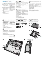
Page 61: ... appears 2 Type idisman and press the Enter key on the keyboard A small dialog box appears 3 Move to Automatic Shutdown and check the box to shutdown the DVR when you end SmartGuard If this box is not checked the DVR will enter the Windows mode via the SmartShell when shutting down SmartGuard 4 You can save your changes by clicking the OK button Selecting Cancel exits the dialog box without saving...

Page 62: ...ation Menu Startup Configures the startup programs of the DVR Execute Menu Restart All Restarts the programs SmartSetup Enters the SmartSetup program to set up the IBank the database of the DVR Ask your system administrator for details about the IBanks setup SmartScan This is invisible software that scans the hard disk drive for recording SmartGuard Enters the SmartGuard program SmartSearch Enters...

Page 63: ...g Menu SmartGuard Displays the log file that logs every operation of the DVR System Menu Close Closes SmartShell and accesses Windows Restart Restarts the DVR Shutdown Shuts down the DVR About Menu About Displays the software version information ...

Page 64: ...N or High Speed Internet Then click the right mouse button and select Properties from the menu 3 Check the Internet Protocol TCP IP box and click the Properties button 4 Click the Use the following IP address radio button Enter the IP address Subnet mask and Default gateway acquired from your network administrator You can save your changes by clicking the OK button Selecting Cancel exits the dialo...

Page 65: ...tworking Setup for Remote Access 1 1 In the Windows mode go to Start on the Task Bar and to Control panel Then open Network Connection and double click Creator a new connection 1 2 Click the Next button 1 3 Select Set up an advanced connection and click the Next button 1 4 Select Accept incoming connections and click the Next button ...

Page 66: ...Name and enter the password for Password and Confirm password And then click the Next button CAUTION After you created a new user as pcr user you must change pppuser and ppppass parameters in the www ini file in the root directory of the BASE system to the new user name and password you just created Windows XP does not allow Guest login so we recommend the user to create a new user as pcr user in ...

Page 67: ...check from the Allow callers to access my local area network box Under the TCP IP address assignment click the Specify TCP IP addresses radio box and enter the From as 10 10 10 11 and the To as 10 10 10 12 And then check the Allow calling computer to specify its own IP address box Click the OK button to save the changes and return to the previous dialog box Click the Next button in the New Connect...

Page 68: ...utton 1 13 Make sure that Incoming Connections has been registered 2 Dial up Networking Setup for Callback Function 2 1 In the Windows mode go to Start on the Task Bar and to the Control panel Then open Network Connection Double click Create a new connection 2 2 Click the Next button ...

Page 69: ...ect to the network at my workplace radio box and click the Next button 2 4 Click the Dial up connection radio box and click the Next button 2 5 Enter My Network for the Connection Name and click the Next button 2 6 Click the Next button without any changes ...

Page 70: ... by clicking the Finish button 2 8 Select My Network in the Network Connections dialog box 2 9 Click the Properties button 2 10 Move to the Security tab and click the Advanced custom settings radio button under Security options Then click the Settings button ...

Page 71: ... and click the OK button 2 12 Move to the Networking tab and select PPP Windows 95 98 NT4 2000 Internet for the dial up server type Then check the Internet Protocol TCP IP box and click the Properties button 2 13 Click the Use the following IP address radio box and enter 10 10 10 12 Then click the OK button ...

Page 72: ...he Dial Up Server box and then click the OK button Follow the Windows instructions for installing the necessary software You can save your changes by clicking the OK button Selecting Cancel exits the dialog box without saving the changes 1 2 In the Windows mode go to Start on the Task Bar to Control Panel and to Network 1 3 Under the Configuration tab in the Network dialog box move to Primary Netw...

Page 73: ... radio button Enter the IP address as 10 10 10 10 and the subnet mask as 255 255 255 0 in the text field beside IP Address and Subnet Mask You can save your changes by clicking the OK button If you select OK you might need to allow the system to reboot Selecting Cancel exits the dialog box without saving the changes 1 9 Open My computer on the desktop and select Dial Up Networking Then click Make ...

Page 74: ...or area code that are necessary to dial out 1 12 Click the Finish button Then click the newly created connection icon in the Dial Up Networking window Click the right mouse button and move the cursor to Properties on the menu and click it 1 13 Under the General tab remove the check from the Use area code and Dialing Properties box when using an extension ...

Page 75: ...k the newly created connection icon and try to connect 2 Dial up Networking Setup for Callback Function NOTE Follow the same procedures to set up the adaptor and protocol as used in steps 1 1 to 1 8 in the Dial up Networking Setup for Remote Access section Then proceed to step 2 1 below 2 1 Open My computer on the desktop and select Dial up Networking Click the pull down menu Connection and move t...

Page 76: ...he Windows mode go to Start on the Task Bar and to the Control panel Then open Network Connection Double click Create a new connection 1 2 Click the Next button 1 3 Click the Connect to the network at my workplace radio button and click the Next button 1 4 Click the Dial up connection radio button and click the Next button ...

Page 77: ...n after finishing the new connection wizard The Connect Dial up Connection dialog box appears The instructions after this step are almost identical to Windows 2000 Go to step 1 7 in the Dial up Networking Setup for Windows 2000 BASE system section and follow the instructions 2 Dial up Networking Setup for Callback Function 2 1 In the Windows mode go to Start on the Task Bar and to the Control pane...

Page 78: ...ections and click the Next button The instructions after this step are almost identical to Windows 2000 Go to step 2 3 in the Dial up Networking Setup for Windows 2000 BASE system section and follow the instructions 3 Account Permission in Windows XP 3 1 In the Windows mode go to Start on the Task Bar and to the Control panel Then open the User Accounts ...

Page 79: ...the Windows XP Professional 3 4 Go to the Control Panel and to the Administrative Tools Then open the Local Security Policy 3 5 Go to the Security Settings then to the Local Policies and then to the User Rights Assignment If there is Guest under the Deny access to this Computer from the network item select the Properties after clicking the right mouse button on the target string to open its proper...

Page 80: ...ndows 2000 BASE System 1 Dial up Networking Setup for Remote Access 1 1 In the Windows mode go to Start on the Task Bar to Settings and to Control panel Then open the Network and Dial up Connection Double click Make New Connection 1 2 Click the Next button 1 3 Click the Dial up to private network radio button and click the Next button ...

Page 81: ...ou may make the dial up connection available to all users or keep it for your own use only Click For all users or Only for myself and click the Next button 1 6 Enter My Network as the name for this connection and click the Finish button Double click the newly created connection icon after finishing the network connection wizard ...

Page 82: ... Windows 95 servers box and click the OK button 1 10 Select PPP Windows 95 98 NT4 2000 Internet from a drop down list for the type of dial up server and click the Settings button Remove the check from the Enable software compression box and click the OK button to save the change and return to the Dial up Connection dialog box 1 11 Check the Internet Protocol TCP IP box for the connection component...

Page 83: ...by double clicking it Enter guest for the User name and click the Dial button to connect to the remote system 2 Dial up Networking Setup for Callback Function 2 1 In the Windows mode go to Start on the Task Bar to Settings and to Control panel Then open Network and Dial up Connection Double click Make New Connection 2 2 Click the Next button 2 3 Click the Accept incoming connections radio box and ...

Page 84: ...t an installed modem to use and click the Next button 2 5 Click the Do not allow virtual private connections radio box and click the Next button 2 6 Check the Guest box for the users allowed to connect and click the Next button ...

Page 85: ...option click the Install button and add it by selecting Protocol and clicking the Add button 2 8 Click the Specify TCP IP addresses radio box and enter 10 10 10 10 in the From box and 10 10 10 12 in the To box Check the Allow calling computer to specify its own IP address box and then click the OK button 2 9 Enter the name for the connection and finish the network connection wizard by clicking the...

Page 86: ...tion Sometimes Windows refuses the remote connection even when the telephone line is not busy Try to connect again Problem I cannot hear dial tone Solution Sometimes the modem cannot access a dial tone if your telephone is an extension Follow the instructions below and then try to connect again 1 Go to My Network under Windows Explorer Dial Up Networking click the right mouse button and select Pro...

Page 87: ...me from the remote site Power Button Quits the program Title Bar Displays the ID or the title of the location where the remote system is installed Camera Button Selects a camera and displays the image of a target camera NOTE The camera button illuminates when that camera is displayed on the screen Screen Button Every time this button is clicked the screen mode switches single screen quad 3x3 and 4...

Page 88: ...om the network administrator WebGuard runs automatically NOTE WebGuard only works with Microsoft Internet Explorer and will NOT work with Netscape Web Sever Setup The DVR includes a personal web sever If you do not want to run a web sever turn it off by clicking the Set up Web Sever button under the System tab of the Setup dialog box in the SmartGuard mode and follow the instructions ...

Page 89: ...ptional only for convenience of users using general terminal All digits are used in decimal format Letters are case sensitive Control Flow Every transaction consists of one command and one reply Characters transmitted before BOM are ignored The format of operands is defined independently for each op code The BOM received before Checksum of the previous message resets interpretation i e discards th...

Page 90: ...ault ID Recorder Player Functions Function Code Operands Reply Reply data Recording On Off RO Y N T on off toggle Panic PN Y N T on off toggle Playback PL F B direction 1 9 speed Playback Still PS A Z F B P Svi Screen Mode RM Show Search PR Alarm Functions Function Code Operands Reply Reply data Alarm Mutevii AU 00 99 AA id viii Y N T on off toggle Alarm Outix AO 00 99 AA id Alarm Resetx AR 00 99 ...

Page 91: ...ixed but determined by preceding operand ii Only 24hour format is supported ex 20000603135030 iii The text can include special characters iv Next 0 Full 1 2x2 2 3 4 3 3x3 4 2 8 5 1 12 6 4x4 7 PIP 8 v 0 for turning off digital zoom others for 2x 16x zoom vi A Z F B P S first last forward backward pause stop vii Alarm Mute alarm out is off while Alarm Mute is on regardless of alarm status viii 00 99...

Page 92: ...O BOARD Ver 1 0 25 Pin DB Connector pin out configuration 1 2 3 4 5 6 7 8 9 10 11 12 13 14 15 16 17 18 19 20 21 22 23 24 25 AL_1 AL_3 GND AL_6 AL_8 AL_9 AL_11 GND AL_14 AL_16 NC COM A_RST AL_2 AL_4 AL_5 AL_7 GND AL_10 AL_12 AL_13 AL_15 GND NO GND AL 1 AL 16 Alarm Inputs 1 to 16 GND Ground COM Relay Common NC Relay Normally Closed NO Relay Normally Open A_RST Reserved Not Supported for Alarm Reset ...

Page 93: ...me Sync button Move to Server and enter the IP address of target time server If you want to synchronize the time between the POST system and a time server automatically check the Automatic box otherwise synchronize the time manually by clicking the Sync now button The user can set up the synchronization interval from 1 to 300 minutes NOTE When selecting Automatic automatic time synchronization the...

Page 94: ... server time If the server time is earlier than the current DVR time you must delete images dated later than the server time If you do not delete images the time cannot be reset NOTE When setting up time synchronization for the first time set the time between the system and the time server manually because the system and the server might have wide time gap ...

Page 95: ...with the System tools under Programs Accessories in Windows 3 Install the new software Problem The IDIS logo appears and then freezes Sometimes the screen is black Solution There is a problem with the Main Board Reboot the DVR If it happens often call your dealer or installer Problem The Display setup is not correct error message appears and opens up in the Windows mode when OK is clicked Solution...

Page 96: ...n or microphone in Audio Out One line out Alarms Terminal block Ethernet Port RJ 45 RS232 Serial Port DB9 P USB Port Four USB connectors Parallel Port 25 P D Sub STORAGE Primary Storage EIDE hard disk drives Secondary Storage Internal DVR RAM External SCSI hard disk drives USB hard disk drives Backup Storage CD RW GENERAL Dimensions W x H x D 16 7 x 6 3 x 17 7 425mm x 160mm x 450mm Unit Weight 25 ...

Reviews: