Stack ST8380, User Manual
The Stack ST8380 User Manual is your comprehensive guide to optimizing and maximizing your product usage. Download this manual for free at manualshive.com and gain instant access to step-by-step instructions, troubleshooting tips, and valuable insights to ensure a seamless experience with your Stack ST8380 device.
Share
Download


Reviews:
No comments
Related manuals for ST8380

16CH AHD DVR
Brand: AtVideo Pages: 123

MINI DVR
Brand: night goggles Pages: 15

500619 - AV420 Pocket Video Recorder
Brand: Archos Pages: 2

STANDALONE DVR HSDVR-3308A
Brand: HEXA Pages: 64
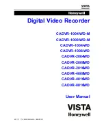
CADVR-1004-WD
Brand: Honeywell Pages: 63

H.264 HRDP
Brand: Honeywell Pages: 106
EVOLUTION 2
Brand: Honeywell Pages: 2

Fusion IV
Brand: Honeywell Pages: 150

FUSION III DVR
Brand: Honeywell Pages: 168

FUSION
Brand: Honeywell Pages: 168

HD-DVR-1004
Brand: Honeywell Pages: 182

HD-16DVR-C
Brand: Honeywell Pages: 169
HDVR
Brand: Honeywell Pages: 238

CADVR-04D
Brand: Honeywell Pages: 240

HRDV 16 Duplex
Brand: Honeywell Pages: 2

PIX 250i
Brand: Sound Devices Pages: 84

SHR-5080
Brand: Samsung Pages: 1

SHR-2160
Brand: Samsung Pages: 1


