Troubleshooting by Error Code
SiUS371901EB
289
Part 6 Service Diagnosis
U7 - 01
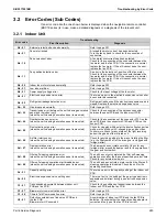
Error when external control adaptor for outdoor unit is
installed
Refer to the
U7
flowchart and make a diagnosis of the
relevant unit based on the Error code shown to the left.
U7 - 02
Warning when external control adaptor for outdoor unit is
installed
U7 - 03
Transmission error between master and slave 1 units
U7 - 04
Transmission error between master and slave 2 units
U7 - 05
Multi system error
U7 - 06
Error in address settings of slave 1 and 2
U7 - 07
Connection of four or more outdoor units in the same
system
U7 - 11
Error in indoor unit connection capacity for test operation
U7 - 24
Defective Branch Selector unit external control adaptor
U9 - 01
Other indoor units abnormality
Refer to the
U9
flowchart and make a diagnosis of the
relevant unit based on the Error code shown to the left.
UA - 17
Connection of excessive indoor units
Refer to the
UA
flowchart and make a diagnosis of the
relevant unit based on the Error code shown to the left.
UA - 18
Connection of wrong models of indoor units
UA - 20
Improper combination of outdoor units
UA - 21
Connection error
UA - 23
Connection of excessive Branch Selector units
UA - 25
Defective connection between outdoor unit and Branch
Selector unit
UA - 26
Defective connection between Branch Selector units
UA - 27
Error of the number of connected Branch Selector and
outdoor units
UA - 28
Wrong Branch Selector unit model connected
UA - 31
Multi-unit combination error
UA - 53
Branch Selector unit DIP switch settings error
(Centralized type)
UF - 01
Wrong wiring check error
Refer to the
UF
flowchart and make a diagnosis of the
relevant unit based on the Error code shown to the left.
UF - 05
Defective stop valve for test operation
UH - 01
Wiring error
Refer to the
UH
flowchart and make a diagnosis of the
relevant unit based on the Error code shown to the left.
Error code
Troubleshooting
Error Description
Diagnosis
Summary of Contents for REYQ72-432XAYCU
Page 455: ...SiUS371901EB Wiring Diagrams Part 7 Appendix 448 REYQ144 168XATJU REYQ144 168XATJA 2D119206B ...
Page 457: ...SiUS371901EB Wiring Diagrams Part 7 Appendix 450 REYQ144 168XAYDU REYQ144 168XAYDA 2D119208C ...
Page 461: ...SiUS371901EB Wiring Diagrams Part 7 Appendix 454 FXZQ05 07 09 12 15 18TAVJU 3D110443A ...
Page 463: ...SiUS371901EB Wiring Diagrams Part 7 Appendix 456 FXEQ07 09 12 15 18 24PVJU 3D098557A ...
Page 464: ...Wiring Diagrams SiUS371901EB 457 Part 7 Appendix FXDQ07 09 12 18 24MVJU C 3D050501C ...
Page 468: ...Wiring Diagrams SiUS371901EB 461 Part 7 Appendix FXHQ12 24 36MVJU 3D048116C ...
Page 469: ...SiUS371901EB Wiring Diagrams Part 7 Appendix 462 FXAQ07 09 12 18 24PVJU 3D075354F ...
Page 475: ...SiUS371901EB Wiring Diagrams Part 7 Appendix 468 VAM1200GVJU 3D073270D ...
Page 478: ...Wiring Diagrams SiUS371901EB 471 Part 7 Appendix BS6 8Q54TVJ 2D089122B ...
Page 479: ...SiUS371901EB Wiring Diagrams Part 7 Appendix 472 BS10 12Q54TVJ 2D089121B ...
Page 481: ...SiUS371901EB Wiring Diagrams Part 7 Appendix 474 BSF6 8Q54TVJ 2D123905A ...


