Viewing Statistics
Managing RMON Statistics
Page 243
Defining RMON Alarms
The
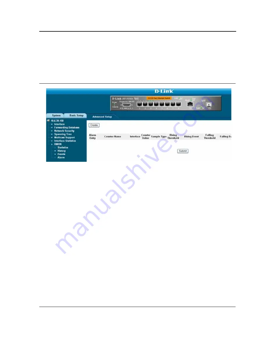
RMON Alarm Page
contains fields for setting network alarms. Network alarms occur when a network
problem, or event, is detected. Rising and falling thresholds generate events. To set RMON alarms:
1.
Click
Advanced Setup > RMON > Alarm
. The
RMON Alarm Page
opens.
Figure 156:RMON Alarm Page
The
RMON Alarm Page
contains the following fields:
•
Alarm Entry
— Indicates a specific alarm.
•
Counter Name
— Displays the selected MIB variable.
•
Interface
— Displays interface for which RMON statistics are displayed. The possible field values are:
–
Port
— Displays the RMON statistics for the selected port.
–
LAG
— Displays the RMON statistics for the selected LAG.
•
Counter Value
— Displays the selected MIB variable value.
•
Sample Type
— Defines the sampling method for the selected variable and comparing the value against the
thresholds. The possible field values are:
–
Delta
— Subtracts the last sampled value from the current value. The difference in the values is
compared to the threshold.
–
Absolute
— Compares the values directly with the thresholds at the end of the sampling interval.
•
Rising Threshold
— Displays the rising counter value that triggers the rising threshold alarm. The rising
threshold is presented on top of the graph bars. Each monitored variable is designated a color.
•
Rising Event
— Displays the mechanism in which the alarms are reported. The possible field values are:
–
LOG
— Indicates there is not a saving mechanism for either the device or in the management system. If
the device is not reset, the entry remains in the Log Table.
–
TRAP
— Indicates that an SNMP trap is generated, and sent via the Trap mechanism. The Trap can also
be saved using the Trap mechanism.
–
Both
— Indicates that both the Log and Trap mechanism are used to report alarms.
•
Falling Threshold
— Displays the falling counter value that triggers the falling threshold alarm. The falling
threshold is graphically presented on top of the graph bars. Each monitored variable is designated a color.
•
Falling Event
— Displays the mechanism in which the alarms are reported.
Summary of Contents for 3010F - DES Switch
Page 1: ......
Page 10: ...D Link DES 3010FA GA Installation Guide Page 9 D Link DES 3010FA GA Installation Guide ...
Page 49: ...D Link DES 3010FA GA User Guide Page 48 D Link DES 3010FA GA EWS User Guide ...
Page 251: ...D Link DES 3010FA GA User Guide Page 250 ...
Page 252: ...Contacting D Link Technical Support Page 251 ...
Page 253: ...D Link DES 3010FA GA User Guide Page 252 ...
Page 254: ...Contacting D Link Technical Support Page 253 ...
Page 255: ...D Link DES 3010FA GA User Guide Page 254 ...
Page 256: ...Contacting D Link Technical Support Page 255 ...
Page 257: ...D Link DES 3010FA GA User Guide Page 256 ...
Page 258: ...Contacting D Link Technical Support Page 257 ...
Page 259: ...D Link DES 3010FA GA User Guide Page 258 ...
Page 260: ...Contacting D Link Technical Support Page 259 ...
Page 261: ...D Link DES 3010FA GA User Guide Page 260 ...
Page 262: ...Contacting D Link Technical Support Page 261 ...
Page 263: ...D Link DES 3010FA GA User Guide Page 262 ...
Page 264: ...Contacting D Link Technical Support Page 263 ...
Page 265: ...D Link DES 3010FA GA User Guide Page 264 ...
Page 266: ...Contacting D Link Technical Support Page 265 ...
Page 267: ...D Link DES 3010FA GA User Guide Page 266 ...
Page 268: ...Contacting D Link Technical Support Page 267 ...
Page 269: ...D Link DES 3010FA GA User Guide Page 268 ...
Page 270: ...Contacting D Link Technical Support Page 269 ...
Page 271: ...D Link DES 3010FA GA User Guide Page 270 ...
Page 272: ...Contacting D Link Technical Support Page 271 ...
Page 273: ...D Link DES 3010FA GA User Guide Page 272 ...
Page 274: ...Contacting D Link Technical Support Page 273 ...
Page 275: ...D Link DES 3010FA GA User Guide Page 274 ...
Page 276: ...Contacting D Link Technical Support Page 275 ...


