Non-Overhaul Removal and Replacement
Teledyne Continental Motors, Inc.
TM
10-16
IOF-550 Permold Series Engine Maintenance Manual
1 April 2007
2.
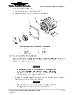
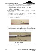
Refer to Figure 10-6; install a new Woodruff key (3), drive hub assembly (5), and
new thrust washer (6).
3.
Install the slotted nut (4).
4.
Secure the tooth portion of the drive hub gear in shielded vise jaws just enough to
prevent the gear from rotating while torquing the slotted nut (4) in the next step.
5.
Torque the slotted nut (4) to the minimum torque value in Appendix B.
6.
If the slots of the nut do not align with the cotter pin hole in the alternator shaft, the
slotted nut may be torqued up to the maximum value in Appendix B. Do not back off
the nut to align the holes.
7.
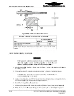
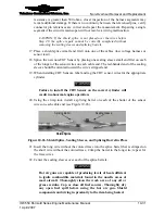
Install the new cotter pin (7) as shown in Figure 10-7, cut and bend the cotter pin to
prevent it from touching the thrust washer to attain clearance when installing the
alternator on the engine.
10-4.2. Direct Drive Alternator Installation
Prior to alternator installation, perform the “Drive Hub Slippage Inspection” in Chapter 7.
Procedure
WARNING
If all power is not disconnected, a loose or broken wire could
allow the engine to start and the propeller to rotate. Do not
stand or place equipment within the arc of the propeller.
1.
Disconnect electrical power to the engine; turn the Ignition Switch OFF.
2.
Inspect the alternator mounting studs for thread condition and security in the
crankcase. Replace damaged or loose studs according to Appendix C instructions.
3.
Install a new gasket (1) on the alternator mounting studs.
4.
Install the alternator on the mounting studs with four plain washers (8) four
new
lock
washers (9), and four nuts (10). Torque the nuts per Appendix B.
5.
If the alternator had a grounding strap when it was removed, install the grounding
strap when installing the alternator.
6.
Reconnect electrical connections at the alternator according to the airframe
manufacturer’s instructions.
7.
Reconnect the aircraft battery per Aircraft Maintenance Manual instructions.
8.
Perform and “Engine Start” according to instructions in Chapter 7 of OI-24 and verify
proper alternator output according to the Aircraft Maintenance Manual.

