Teledyne Continental Motors, Inc.
TM
Troubleshooting
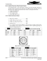
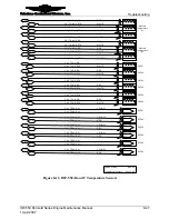
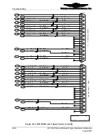
Figure 8-3.
P7 Connector Pin Layout
P7 Connector Signals
P7 Connector Signals
A
Primary Power
L
Mix 34 SIG
A
Primary Power
L
Enable B
B
Ground
M
Mix 34 RET
B
Ground
M
Fault 4
C
Secondary Power
N
Fuel Pump
C
Primary Power
N
Enable B
D Ground
P NC*
D Ground
P Fault
6
E
RS485A
R
Primary Power
E
Primary Power
R
Mix 34
F RS485B
S Ground
F Ground
S Fuel
Pump
2
G Fault
C
T *NC
G RS485A
T Mix
56
H
Fault D
U
Secondary Power
H
RS485B
U
Fuel Pump 3
J Enable
C
V Ground
J Enable
B
V *NC
K Enable
D
K Fault
2
*NC – Not Connected
B C
N P R
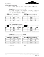
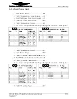
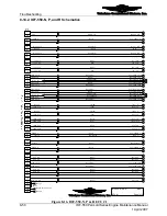
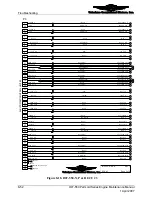
Figure 8-4.
P8 Connector Pin Layout
NOTE: P8 is not used on the IOF-550-N, P, and R engine low
voltage harness.
P8 Connector Signals
A
Primary Power
L
Mix 56 SIG
B
Ground
M
Mix 56 RET
C
Secondary Power
N
Fuel Pump
D Ground
P NC*
E RS485A
R NC*
F RS485B
S NC*
G Fault
E
T NC*
H Fault
F
U NC*
J Enable
E
V NC*
K Enable
F
*NC – Not Connected
B C
IOF-550 Permold Series Engine Maintenance Manual
8-37
1 April 2007


