Teledyne Continental Motors, Inc.
TM
Non-Overhaul Removal and Replacement
IOF-550 Permold Series Engine Maintenance Manual
10-43
1 April 2007
7.
Using a DVM, measure the resistance between the SSA sensor body and airframe
electrical ground bus. Resistance must be less than 0.5 ohms.
8.
Connect the SSA 25-pin connectors according to instructions in Section 10-6.1,
“ECU or SSA Connector Installation.”
9.
Perform an SSA Operational Check according to section 10-6.8 instructions to verify
SSA functionality.
10-6.8.
SSA Operational Check
Procedure
1.
Turn Aircraft Master Power Switch, Ignition Switch, and the FADEC Primary Power
and Secondary Power Switches to the OFF position.
2.
Disconnect the high voltage harness and remove the top spark plugs from all
cylinders; see “Ignition System Maintenance” in Chapter 9 for removal instructions.
NOTE: The N
c
and N
e
switches enable audio associated with LED
illumination. Position all N
c
and N
e
switches closest to its
representative LED indicator to turn off audio.
3.
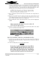
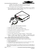
Disconnect both of the Engine Low Voltage Harness 25-pin connectors from the
signal conditioner. Plug the 25-pin connector of the FADEC Timing Tool as shown in
Figure 10-39 into one of the 25-pin headers on the SSA signal conditioner.
To signal
conditioner
To signal
conditioner
To signal
conditioner
Figure 10-39.
FADEC Timing Tool to Signal Conditioner
4.
Turn on the FADEC Timing Tool by sliding the power switch toward the top of the
tester. The power LED will illuminate to indicate power is on. The N
c
and N
e
LED
state will depend on sensor position in relation to the camshaft. LEDs are normally
ON; as the holes in the camshaft pass the sensor, the LED will extinguish
momentarily.
WARNING
Make sure all personnel are standing clear of the propeller’s
path of rotation to avoid injury.
C
B


