Engine Description
Teledyne Continental Motors, Inc.
TM
2-2
IOF-550 Permold Series Engine Maintenance Manual
1 April 2007
LIST OF FIGURES
Figure 2-1. Engine Model Identifier ............................................................................................ 2-4
Figure 2-2. Cylinder Number Designation .................................................................................. 2-4
Figure 2-3. Crankcase .................................................................................................................. 2-5
Figure 2-4. Engine Drive Train.................................................................................................... 2-6
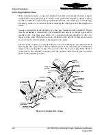
Figure 2-5. Crankshaft ................................................................................................................. 2-7
Figure 2-6. Updraft Cylinder Assembly .................................................................................... 2-10
Figure 2-7. Cross-flow Cylinder Assembly ............................................................................... 2-10
Figure 2-8. Lubrication Schematic ............................................................................................ 2-12
Figure 2-9. Oil Pump ................................................................................................................. 2-13
Figure 2-10. Oil Cooler.............................................................................................................. 2-15
Figure 2-11. IOF-550-B & C FADEC components................................................................... 2-17
Figure 2-12. IOF-550-N, P & R FADEC components .............................................................. 2-18
Figure 2-13. Two-Lamp HSA Panel.......................................................................................... 2-21
Figure 2-14. HSA with Battery Condition Monitor Panel......................................................... 2-21
Figure 2-15. Engine Control Panel ............................................................................................ 2-22
Figure 2-16. Engine Data Interface............................................................................................ 2-22
Figure 2-17. IOF-550-B & C Fuel Injection System ................................................................. 2-23
Figure 2-18. IOF-550 N, P & R Fuel Injection System............................................................. 2-24
Figure 2-19. Fuel Pump ............................................................................................................. 2-25
Figure 2-20. FADEC Fuel Injector and Solenoid ...................................................................... 2-26
Figure 2-21. Starting System ..................................................................................................... 2-27
Figure 2-22. Engine Cooling Airflow........................................................................................ 2-28
Figure 2-23. IOF-550-B Updraft Induction Airflow.................................................................. 2-29
Figure 2-24. Downdraft (Crossflow) Induction Airflow ........................................................... 2-30
Figure 2-25. IOF-550-B and C Fuel Flow vs. Brake Horsepower............................................. 2-39
Figure 2-26. IOF-550-B and C Sea Level Performance ............................................................ 2-40
Figure 2-27. IOF-550-N, P, and R Full Rich Fuel Flow vs. Brake Horsepower ....................... 2-41
Figure 2-28. IOF-550-N, P, and R Full Rich Sea Level Performance....................................... 2-42


