Troubleshooting
Teledyne Continental Motors, Inc.
TM
8-13.2. Enable Switch Check
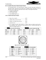
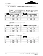
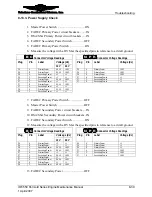
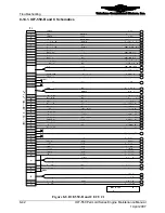
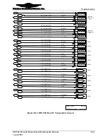
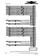
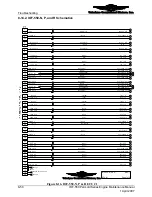
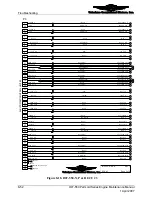
Refer to the connector pin layout diagrams in Figure 8-2, Figure 8-3, and Figure 8-4.
Procedure
1.
Ignition Switch.................................................. L
2.
Use a DVM to measure the resistance for the pin numbers listed in reference to
aircraft ground. For each item in the table, insert one lead of the Pin Test Kit into the
socket of the 19-pin connector being checked.
Connector Resistance Readings
Connector
Resistance
Readings
Plug Pin
Label
Resistance
Plug Pin
Label
Resistance
P6
J
Enable A
< 0.5
P6
L
Enable A
< 0.5
P6
K
Enable B
OPEN
P6
N
Enable A
< 0.5
P7
J
Enable C
< 0.5
P6
R
Enable A
< 0.5
P7
K
Enable D
OPEN
P7
J
Enable B
OPEN
P8
J
Enable E
< 0.5
P7
L
Enable B
OPEN
P8
K
Enable F
OPEN
P7
N
Enable B
OPEN
B C
N P R
3.
Ignition Switch..................................................R
4.
Check resistance at the following pins:
Connector Resistance Readings
Connector
Resistance
Readings
Plug Pin
Label
Resistance
Plug Pin
Label
Resistance
P6
J
Enable A
OPEN
P6
L
Enable A
OPEN
P6
K
Enable B
< 0.5
P6
N
Enable A
OPEN
P7
J
Enable C
OPEN
P6
R
Enable A
OPEN
P7
K
Enable D
< 0.5
P7
J
Enable B
< 0.5
P8
J
Enable E
OPEN
P7
L
Enable B
< 0.5
P8
K
Enable F
< 0.5
P7
N
Enable B
< 0.5
B C
N P R
5.
Ignition Switch .........................................BOTH
6.
Check resistance at the following pins:
Connector Resistance Readings
Connector
Resistance
Readings
Plug Pin
Label
Resistance
Plug Pin
Label
Resistance
P6
J
Enable A
OPEN
P6
L
Enable A
OPEN
P6
K
Enable B
OPEN
P6
N
Enable A
OPEN
P7
J
Enable C
OPEN
P6
R
Enable A
OPEN
P7
K
Enable D
OPEN
P7
J
Enable B
OPEN
P8
J
Enable E
OPEN
P7
L
Enable B
OPEN
P8
K
Enable F
OPEN
P7
N
Enable B
OPEN
B C
N P R
7.
Ignition Switch............................................. OFF
8-38
IOF-550 Permold Series Engine Maintenance Manual
1 April 2007


