Torque Specifications
Teledyne Continental Motors, Inc.
TM
B-12
IOF-550 Permold Series Engine Maintenance Manual
1 April 2007
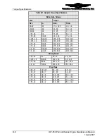
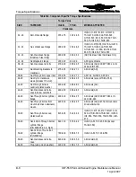
Table B-5.
Specific Torque Values for Non-lubricated Hardware
Torque
Location and Hardware
Model
Thread
Qty.
In-lbs
Ft-lbs
Oil pressure relief valve
Housing
All
1.12-18
1
240-260
20.0-21.7
Oil temperature control
valve
---- All
1.00-14
1
440-460
36.7-38.3
Fuel nozzle to cylinder
Nozzle All
0.125-27
(dry seal)
6 55-65 4.6-5.4
Fuel injection line to fuel
nozzles
“B” Nut
All
0.31-32
6
40-45
3.3-3.8
Fuel injection line to fuel
distribution block
Nut, union
All
0.375-24
6
55-60
4.6-5.0
Fuel injection solenoid nut
Retaining nut All FADEC .3125-32
6
24-28
2.0-2.3
Lead to spark plug
`'B” nut
All
0.75-20
12
110-120
9.2-10.0
Throttle lever
Screw
All
8-32
1
17.5-22.5
1.5-1.9
Apply Loctite Pipe Sealant 592
Apply F/I Sealant TCM part number 646940 or Loctite 569 Hydraulic Sealant
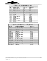
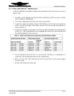
Table B-6.
FADEC Components
Hardware
Engine Model
Torque
(in-lbs)
ECU 50-pin Connector Securing Screws
All
10 -15
Signal Conditioner 25-pin Connector Securing Screws
All
10 -15
Fuel Pressure Sensors
All
130 -150
Manifold Pressure Sensors
All
130 -150
Cylinder Head Temperature Sensor
All
55 - 65
Manifold Air Temperature Adapter (Sensor Nut)
All
70 -120
Manifold Air Temperature Compression Fitting (Ferrule Nut)
All
145 -155
Exhaust Gas Temperature Sensor Band Clamp
All
30 - 35
Lead to ECU spark tower “B” Nut
All
110 -120
NOTE: All hardware in this table is non-lubricated


