Troubleshooting
Teledyne Continental Motors, Inc.
TM
8-20
IOF-550 Permold Series Engine Maintenance Manual
1 April 2007
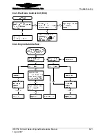
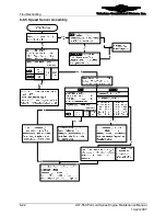
8-6.2. FADEC System Fault Isolation
When troubleshooting the FADEC System, visualize the system as being composed of
the following four major sub-systems:
•
Electronic Control Units (ECUs)
•
The ECUs are the FADEC System computers. One ECU controls two cylinders.
•
High Voltage Harness
•
The high voltage harness connects the ECU spark towers to the spark plugs.
•
Engine Low Voltage Harness
•
The engine low voltage harness connects the ECUs with the sensor set, pilot
interface devices, and the electrical power sources.
•
Sensor Set
The FADEC sensor set includes all sensors used by the FADEC System to monitor
engine performance. Some sensors are “hard-wired” into the engine low voltage
harness while others utilize quick disconnects to interface with the engine low voltage
harness. For optimum FADEC System performance, all sensors must be operational.
A FADEC malfunction typically can be traced to one of the four sub-systems. Each ECU
control channel has a unique cylinder head and exhaust gas temperature sensor. The ECU
control channels share the following sensors.
•
CHT Sensors (in quantities corresponding to the number of engine cylinders)
•
EGT Sensors (in quantities corresponding to the number of engine cylinders)
•
Two Manifold Air Temperature Sensors
•
Sensor 1
Odd-numbered control channels
•
Sensor 2
Even-numbered control channels
•
Two Manifold Air Pressure Sensors
•
Sensor Connector J3 Odd-numbered control channels
•
Sensor Connector J4 Even-numbered control channels
•
Two Fuel Pressure Sensors
•
Sensor Connector J1 Odd-numbered control channels
•
Sensor Connector J2 Even-numbered control channels
•
Speed Sensor Assembly
•
Sensor Pair 1 Channels 1 and 4
•
Sensor Pair 2 Channels 2 and 5
•
Sensor Pair 3 Channels 3 and 6
•
Best Power/Best Economy Switch
Each control channel performs diagnostic checks on itself and the sensors it utilizes. If a
fault with one of the sensors is detected, an HSA lamp will be illuminated. A computer
with the TCM FADEC Level I Diagnostics Software installed can be used to
communicate with each control channel and display detected sensor faults. Refer to
schematics in the back of this chapter to aid in tracing electrical signals.


