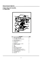
2 Unpacking and Assembly
5
2.2 Assembly of Display Column
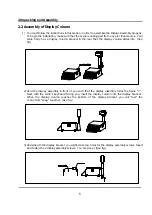
1) You must follow the instructions in this section in order to assemble the Display Assembly properly.
To begin the installation, make sure that the scale is unplugged from any electrical source. Your
scale body has a display column bracket in the rear that the display column slides into. (See
fig.)
2) Hold the display assembly in front of you such that the display assembly forms the figure “7”.
Next, with the scale’s keyboard facing you, insert the display column into the display bracket.
When the display column reaches the bottom of the display bracket, you will “feel” the
connectors “snap” together. (See fig.)
3) Underneath the display bracket you will find 2 screw holes for the display assembly screws. Insert
and fasten the 2 display assembly screws. You are done! (See fig.)
Summary of Contents for LP-2G
Page 2: ......
Page 8: ......
Page 11: ...1 General 3 Note Specifications are subject to change without notice ...
Page 46: ...11 Network Options 38 11 Network Options Refer to Network manual ...
Page 66: ...16 Troubleshooting 58 16 2 Versioning Changes ...
Page 69: ...17 Schematic Diagrams 61 17 3 Main PCB ...
Page 70: ...17 Schematic Diagrams 62 17 4 Ethernet Memory Expansion PCB ...
Page 71: ...17 Schematic Diagrams 63 17 5 Power Supply PCB ...
Page 72: ...18 Exploded Views 64 18 Exploded Views 18 1 Scale ...
Page 73: ...18 Exploded Views 65 18 2 Printer Assembly ...
Page 74: ......
Page 89: ...Appendix C 85 ...
Page 90: ...Appendix C 86 ...
Page 91: ...Appendix C 87 ...
Page 92: ...Appendix C 88 ...
Page 93: ...Appendix C 89 ...
Page 94: ...Appendix C 90 ...
Page 95: ...Appendix C 91 ...
Page 96: ...Appendix C 92 ...
Page 97: ...Appendix C 93 ...
Page 98: ...Appendix C 94 ...
Page 99: ...Appendix C 95 ...
Page 100: ...Appendix C 96 ...
Page 101: ...Appendix C 97 ...
Page 102: ...Appendix C 98 ...
Page 103: ...Appendix C 99 ...
Page 104: ...Appendix C 100 ...


