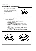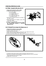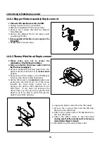
10 Printer Hardware Settings
35
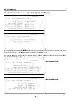
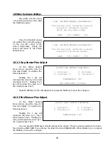
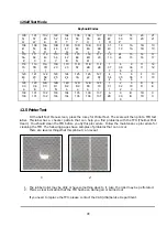
< CAL: PRINTER SENSOR CALIBRATION >
The Printer will calibrate sensors
and print threshold values.
Press any key when ready.
GAP= 100 PEEL= 151
< CAL: PRINTER SENSOR CALIBRATION >
The Printer will calibrate sensors
and print threshold values.
GAP= 102 PEEL= 150
ADJUST GAP SENSOR THRESHOLD
1. Decrease 3. Increase
2. Decrease 5 4. Increase 5
THRESHOLD= 200
USE FEED KEY TO TEST
ADJUST PEEL SENSOR THRESHOLD
1. Decrease 3. Increase
2. Decrease 5 4. Increase 5
THRESHOLD= 125
The printer will then feed
out several labels and then print
the threshold values.
Once the threshold values
are printed they will also appear
on the top left corner of the
screen temporarily. Finally, the
screen will return to the Printer
Sensors menu.
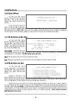
10.2.2 Gap Sensor Fine Adjust
At the Printer Sensors
Menu screen, press the 2 key for
Fine Gap Adjust. You will see the
following screen:
Pressing the 1 key will
decrease the value by 1; the 2 will
decrease it by 5. Pressing the 3
key will increase the value by 1;
the 4 will increase it by 5.
Press the FEED key to the test alignment or press the SAVE key to save the changes.
10.2.3 Peel Sensor Fine Adjust
At the Printer Sensors
Menu screen, press the 3 key for
Fine Peel Adjust. You will see the
following screen:
Pressing the 1 key will
decrease the value by 1; the 2
will decrease it by 5. Pressing the
3 key will increase the value by 1;
the 4 will increase it by 5.
You can press the FEED key to test the status of the sensor: if there is a label waiting to be taken
then it will read BLOCKED; if you remove the label it will read UNBLOCKED. When finished, you can press
the SAVE key to save the changes.
Summary of Contents for LP-2G
Page 2: ......
Page 8: ......
Page 11: ...1 General 3 Note Specifications are subject to change without notice ...
Page 46: ...11 Network Options 38 11 Network Options Refer to Network manual ...
Page 66: ...16 Troubleshooting 58 16 2 Versioning Changes ...
Page 69: ...17 Schematic Diagrams 61 17 3 Main PCB ...
Page 70: ...17 Schematic Diagrams 62 17 4 Ethernet Memory Expansion PCB ...
Page 71: ...17 Schematic Diagrams 63 17 5 Power Supply PCB ...
Page 72: ...18 Exploded Views 64 18 Exploded Views 18 1 Scale ...
Page 73: ...18 Exploded Views 65 18 2 Printer Assembly ...
Page 74: ......
Page 89: ...Appendix C 85 ...
Page 90: ...Appendix C 86 ...
Page 91: ...Appendix C 87 ...
Page 92: ...Appendix C 88 ...
Page 93: ...Appendix C 89 ...
Page 94: ...Appendix C 90 ...
Page 95: ...Appendix C 91 ...
Page 96: ...Appendix C 92 ...
Page 97: ...Appendix C 93 ...
Page 98: ...Appendix C 94 ...
Page 99: ...Appendix C 95 ...
Page 100: ...Appendix C 96 ...
Page 101: ...Appendix C 97 ...
Page 102: ...Appendix C 98 ...
Page 103: ...Appendix C 99 ...
Page 104: ...Appendix C 100 ...


