4 Nomenclature
10
4.2 Display and Indicators
1)
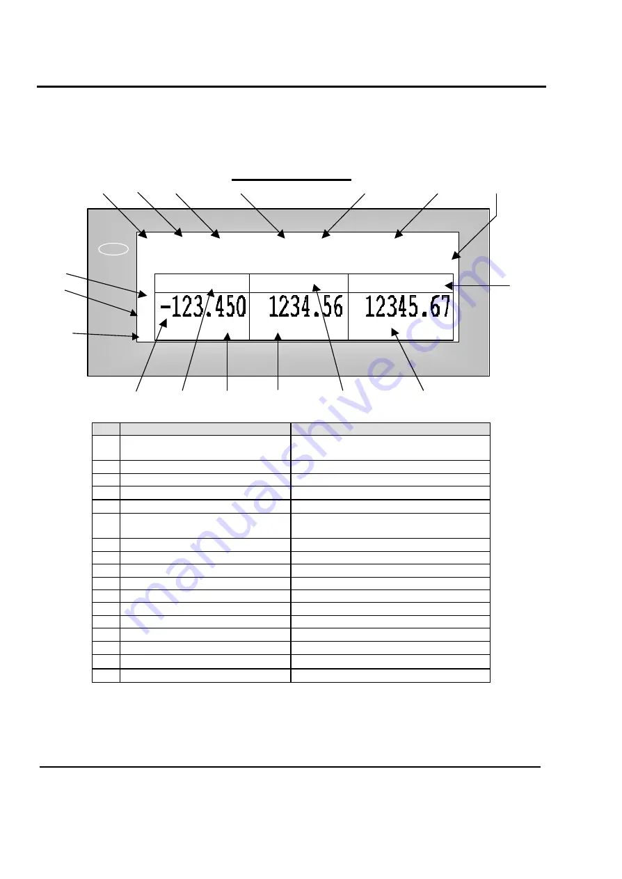
VF Display:
The front and rear displays on the LP-2 are dot matrix vacuum fluorescent displays.
They will display all information pertinent to operating the scale.
LP-2 Display Window: Sales
1
2
3
4
5
6
7
17
16
8
15
14
13
12
11
10
9
#
Description
Values
1 Mode indicator
REG, RPK, MGR, ADD, PLU, NET
1
, STR
2
,
LOC, SET, X1, X2, Z1, Z2
2 Print Mode indicator
Auto
3 Auto Clearing status indicator
PrePack, Save,
(Blank)
4 Speed key Shift status indicator
Shift,
(Blank)
5 Override & Discount Status
Ride, DISC, Disc, 1, 2, 3,
(Blank)
6 Multi-function indicator
Time, date, scale #, department #,
Alt, Temporary Changes, (Blank)
7 PLU Description line
First non-blank line of PLU commodity
8 Total price heading
TOTAL PRICE
and money symbol
9 Total price indicator
7 digits USA: 0.00~9999.99
10 Unit price heading
UNIT,
money and weigh symbols
11 Unit price indicator
6 digits USA: 0.00~999.99
12 Weight indicator
5 digits
13 Weight heading
WEIGHT
and weigh symbol
14 Negative weight indicator
-,
(Blank)
15 Net-Weight indicator
◀
,
(Blank)
16 Stable weight indicator
○
,
(Blank)
17 Zero weight indicator
◀
,
(Blank)
A Gross Zero indication is reached when the Net -Weight indicator is OFF, the Zero-Weight indicator is ON,
the Stable indicator is ON, and the weight reads 0.00 or 0.000.
NOTE
1
:
Only on networking scales.
NOTE
2
:
Only on stand-alone scales.
WEIGHT kg
UNIT $ / kg
TOTAL PRICE $
◀
○
◀
<REG> Auto PrePack Shift Ride 12:12:00 PM
This is PLU Commodity Nam
I
0~30 lb x 0.01 lb / 30~60 lb x 0.02 lb, e=d=0.01 lb, 0.02 lb
0~15 kg x 0.005 kg / 15~30 kg x 0.01 kg, e=d=5g, 10g
CAPACITY:
ZERO
STABLE
NET
Summary of Contents for LP-2G
Page 2: ......
Page 8: ......
Page 11: ...1 General 3 Note Specifications are subject to change without notice ...
Page 46: ...11 Network Options 38 11 Network Options Refer to Network manual ...
Page 66: ...16 Troubleshooting 58 16 2 Versioning Changes ...
Page 69: ...17 Schematic Diagrams 61 17 3 Main PCB ...
Page 70: ...17 Schematic Diagrams 62 17 4 Ethernet Memory Expansion PCB ...
Page 71: ...17 Schematic Diagrams 63 17 5 Power Supply PCB ...
Page 72: ...18 Exploded Views 64 18 Exploded Views 18 1 Scale ...
Page 73: ...18 Exploded Views 65 18 2 Printer Assembly ...
Page 74: ......
Page 89: ...Appendix C 85 ...
Page 90: ...Appendix C 86 ...
Page 91: ...Appendix C 87 ...
Page 92: ...Appendix C 88 ...
Page 93: ...Appendix C 89 ...
Page 94: ...Appendix C 90 ...
Page 95: ...Appendix C 91 ...
Page 96: ...Appendix C 92 ...
Page 97: ...Appendix C 93 ...
Page 98: ...Appendix C 94 ...
Page 99: ...Appendix C 95 ...
Page 100: ...Appendix C 96 ...
Page 101: ...Appendix C 97 ...
Page 102: ...Appendix C 98 ...
Page 103: ...Appendix C 99 ...
Page 104: ...Appendix C 100 ...

