9 Digital Filtering
33
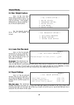
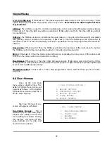
NUMERIC
< CAL: DIGITAL FILTERING >
Motion Band : [ 3] COUNTS
Filter Band : [10] COUNTS
Filter Sample Times : [ 8]
9 Digital Filtering
9.1 Digital Filter Settings
Once at the CAL Main
menu screen, turn
CAL switch
on
and press the 3 key. The Digital
Filtering screen will appear as
follows:
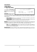
Motion Band:
This value is used to
set the scales stability lamp. It
can be from 0 to 50 but should never be less than 3. When the scale weight is stable, the stable symbol
Î
is on; when the scale is unstable the stable symbol is off. Higher value makes the weighing more
stable but slower.
•
Stable to Unstable:
If there are 2 consecutive load cell readings whose difference is greater than
the Motion Band, then the stable lamp is shut off.
•
Unstable to Stable:
If there are 4 consecutive load cell readings whose difference between any
pair is less than or equal to the Motion Band, then the stable lamp is turned on.
Filter Band:
This value is used to filter out small vibrations from noisy environments. It can be from 0 to 50
but should not be less than 10. The filter will also affect stability: the more filtering the more stable the
scale appears. Higher values will filter out more noise but will slow the weight response time.
•
Filter:
If there are Filter Sample Times number of consecutive load cell readings whose difference
is greater than the Filter Band, then they are not filtered; if they are less than or equal to the Filter
Band, then they are averaged together.
Filter Sample Times:
This value controls the number of readings that the Filter Band uses. It can be from
0 to 16 but should not be less than 8. Higher values will smooth out sharp weight changes due to noise.
Summary of Contents for LP-2G
Page 2: ......
Page 8: ......
Page 11: ...1 General 3 Note Specifications are subject to change without notice ...
Page 46: ...11 Network Options 38 11 Network Options Refer to Network manual ...
Page 66: ...16 Troubleshooting 58 16 2 Versioning Changes ...
Page 69: ...17 Schematic Diagrams 61 17 3 Main PCB ...
Page 70: ...17 Schematic Diagrams 62 17 4 Ethernet Memory Expansion PCB ...
Page 71: ...17 Schematic Diagrams 63 17 5 Power Supply PCB ...
Page 72: ...18 Exploded Views 64 18 Exploded Views 18 1 Scale ...
Page 73: ...18 Exploded Views 65 18 2 Printer Assembly ...
Page 74: ......
Page 89: ...Appendix C 85 ...
Page 90: ...Appendix C 86 ...
Page 91: ...Appendix C 87 ...
Page 92: ...Appendix C 88 ...
Page 93: ...Appendix C 89 ...
Page 94: ...Appendix C 90 ...
Page 95: ...Appendix C 91 ...
Page 96: ...Appendix C 92 ...
Page 97: ...Appendix C 93 ...
Page 98: ...Appendix C 94 ...
Page 99: ...Appendix C 95 ...
Page 100: ...Appendix C 96 ...
Page 101: ...Appendix C 97 ...
Page 102: ...Appendix C 98 ...
Page 103: ...Appendix C 99 ...
Page 104: ...Appendix C 100 ...


