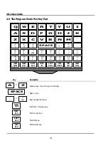
5 Getting Started
17
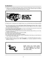
3) Take the new roll of labels and find the ending. Peel-off and discard about one foot (12 inches) of
labels from the backing before installing the roll into the scale. Place the label in the scale as shown
and thread the backing through the appropriate places. (See fig.)
4) Please view the checkpoints on the diagram below as you read these directions to thread the labels.
•
Feed the backing paper over the width-adjusting Pressure Shaft lifting the Pressure Plate in order to
place the backing between the two making sure that the width adjustment is as exact as possible
without bending the backing paper.
‚
Feed the backing paper inside the slot between the Gap sensor assembly making sure that the labels
travel under the Secondary width-adjuster.
ƒ
Make sure that labels are pushed all the way to the left on the Peel-Off bar.
„
Feed the backing over the Rubber Roller and under the Print Head being careful not to touch the
underside of the Print Head.
…
Continue to feed the backing paper over the Peel-off Bar.
†
Continue to feed it under the Return Roller.
‡
Feed the backing under and around the Pick-Up Shaft.
ˆ
Now attach the Pick Up Spool assembly onto the Pick-Up Shaft and turn it slowly counterclockwise in
order to tighten the backing paper.
5) Push the Print Head down in order to lock it back in place. You will feel and hear it lock in place.
Close the printer access pa nel and press the
ON/OFF
key. You have completed the label roll
installation. (See fig.)
MAKE SURE YOU HAVE DONE
THE ADJUSTMENTS AT POINTS
1, 2, AND 3 BEFORE YOU LOCK
THE PRINT HEAD.
Summary of Contents for LP-2G
Page 2: ......
Page 8: ......
Page 11: ...1 General 3 Note Specifications are subject to change without notice ...
Page 46: ...11 Network Options 38 11 Network Options Refer to Network manual ...
Page 66: ...16 Troubleshooting 58 16 2 Versioning Changes ...
Page 69: ...17 Schematic Diagrams 61 17 3 Main PCB ...
Page 70: ...17 Schematic Diagrams 62 17 4 Ethernet Memory Expansion PCB ...
Page 71: ...17 Schematic Diagrams 63 17 5 Power Supply PCB ...
Page 72: ...18 Exploded Views 64 18 Exploded Views 18 1 Scale ...
Page 73: ...18 Exploded Views 65 18 2 Printer Assembly ...
Page 74: ......
Page 89: ...Appendix C 85 ...
Page 90: ...Appendix C 86 ...
Page 91: ...Appendix C 87 ...
Page 92: ...Appendix C 88 ...
Page 93: ...Appendix C 89 ...
Page 94: ...Appendix C 90 ...
Page 95: ...Appendix C 91 ...
Page 96: ...Appendix C 92 ...
Page 97: ...Appendix C 93 ...
Page 98: ...Appendix C 94 ...
Page 99: ...Appendix C 95 ...
Page 100: ...Appendix C 96 ...
Page 101: ...Appendix C 97 ...
Page 102: ...Appendix C 98 ...
Page 103: ...Appendix C 99 ...
Page 104: ...Appendix C 100 ...


