12 Self Test Mode
43
< SERIAL PORT TEST >
Place loopback plug on 9-pin RS-232C port
Press any key when ready.
Press any key when done.
< CAL: FIRMWARE VERSIONS >
ROM DESCRIPTION VERSION CHECKSUM
#1 SCALE SYSTEM ROM 1.00 USA AFA5
#2 SCREEN FONTS ROM 1.00 USA A686
#3 PRINTER FONTS ROM 1.01 USA 9C06
#4 PRINTER SYSTEM ROM 1.01 USA DEDD
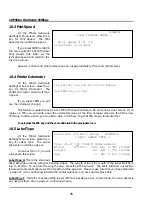
12.9 Serial Port Test
At the Self Test Menu
screen, press the 8 key for Serial
Port Test. The scale will then
display the Serial Port Test screen.
Before you continue from
this screen, you need to place a
loop-back plug on the 9-pin serial
port on the side of the scale. The loop-back plug needs to be a 9-pin male connector with pins 2 & 3
shorted. Once you have done this, press any key. If the serial port is working, you will see the message
“RS-232 Test Passed” on the screen. After a few seconds, it will return to the Self Test Menu. If it fails, you
will see the “RS-232 Test Failed” on the screen. You may press ESC to exit or any key to try again.
If you are having problems with this test, please make sure that the loop-back plug is connected
properly and that it has pins 2 & 3 shorted. If the problem persists, you may have a damaged
connector or serial port driver.
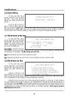
12.10 Firmware Versions Test
At the Self Test Menu
screen, press the 9 key for
Firmware Versions Test. The scale
will then display the Firmware
Versions Test screen.
This test can help you
determine the versions of all of
the scale’s ROMs without having to take the scale apart. This feature can also be accessed from scale
mode by pressing ESC and then HELP. This can also help with customer support over the phone, as it is
not necessary to enter CAL mode to get this information.
ROM #5 may not appear on all versions of LP-
2.
A list of ROM versions, checksums, brief descriptions, and BIN files will be available on our website.
The availability is TBA. As of October 1999, all ROM versions are 1.00.
Summary of Contents for LP-2G
Page 2: ......
Page 8: ......
Page 11: ...1 General 3 Note Specifications are subject to change without notice ...
Page 46: ...11 Network Options 38 11 Network Options Refer to Network manual ...
Page 66: ...16 Troubleshooting 58 16 2 Versioning Changes ...
Page 69: ...17 Schematic Diagrams 61 17 3 Main PCB ...
Page 70: ...17 Schematic Diagrams 62 17 4 Ethernet Memory Expansion PCB ...
Page 71: ...17 Schematic Diagrams 63 17 5 Power Supply PCB ...
Page 72: ...18 Exploded Views 64 18 Exploded Views 18 1 Scale ...
Page 73: ...18 Exploded Views 65 18 2 Printer Assembly ...
Page 74: ......
Page 89: ...Appendix C 85 ...
Page 90: ...Appendix C 86 ...
Page 91: ...Appendix C 87 ...
Page 92: ...Appendix C 88 ...
Page 93: ...Appendix C 89 ...
Page 94: ...Appendix C 90 ...
Page 95: ...Appendix C 91 ...
Page 96: ...Appendix C 92 ...
Page 97: ...Appendix C 93 ...
Page 98: ...Appendix C 94 ...
Page 99: ...Appendix C 95 ...
Page 100: ...Appendix C 96 ...
Page 101: ...Appendix C 97 ...
Page 102: ...Appendix C 98 ...
Page 103: ...Appendix C 99 ...
Page 104: ...Appendix C 100 ...

