9 Digital Filtering
26
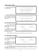
NUMERIC
< CAL: TARE OPTIONS >
Tare
:[0]
0. Full Tare
Tare Mode
:[0]
1. Half Tare
2. Custom Tare
NUMERIC
< CAL: TARE OPTIONS >
Tare
:[0]
0. One Time Tare
Tare Mode
:[0]
1. Successive Tare
NUMERIC
< CAL: TARE OPTIONS >
Tare
:[2]
Tare Mode
:[0]
Maximum Tare
:[60.000] lb
NUMERIC
< CAL: ZERO RANGE >
Initial Zero Range(+,-) :[10]%
ReZero Range (+,-) :[5]%
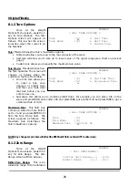
8.1.2 Tare Options
Once at the Weight
Options Menu screen, press the 2
key for Tare Options. The Tare
Options screen will appear as
follows. This is what the screen
looks like when the cursor is on
the Tare field.
Tare:
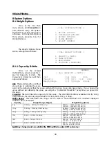
This determines the Tare’s maximum capacity.
•
Full tare will allow you tare up to the max capacity of the scale.
•
Half tare will allow you to tare up to lower value of the upper range (see chart on previous
page.)
•
Custom tare allows you to specify the maximum tare value.
Tare Mode:
This determines how
the Tare operates. The screen will
change as follows when the
cursor is on the Tare Mode field.
•
One time tare allows you
to enter a tare once
(manual or platter tare)
and then you must clear
that tare before you can
enter a new one.
•
Successive tare allows you to combine platter tares. For example, you can place 5 lb on the
scale and press TARE; put another 5 lb and press TARE; put another 5 lb and press TARE to get a
combined tare of 15 lb.
Maximum Tare:
This field only
comes up when the Tare field is
set to 2 and you press ENTER or
↓
from the Tare Mode field. The
screen appears as follows. The
Maximum tare determines the
Tare’s maximum capacity.
NOTE: Any changes made here will affect the NTEP Audit Trail counters (OPT counter only.)
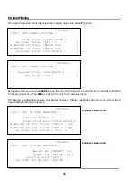
8.1.3 Zero Range
Once at the Weight
Options Menu screen, press the 3
key for Zero Range. The Zero
Range screen will then appear.
Initial Zero Range:
This is an
allowable range from Calibrated
Summary of Contents for LP-2G
Page 2: ......
Page 8: ......
Page 11: ...1 General 3 Note Specifications are subject to change without notice ...
Page 46: ...11 Network Options 38 11 Network Options Refer to Network manual ...
Page 66: ...16 Troubleshooting 58 16 2 Versioning Changes ...
Page 69: ...17 Schematic Diagrams 61 17 3 Main PCB ...
Page 70: ...17 Schematic Diagrams 62 17 4 Ethernet Memory Expansion PCB ...
Page 71: ...17 Schematic Diagrams 63 17 5 Power Supply PCB ...
Page 72: ...18 Exploded Views 64 18 Exploded Views 18 1 Scale ...
Page 73: ...18 Exploded Views 65 18 2 Printer Assembly ...
Page 74: ......
Page 89: ...Appendix C 85 ...
Page 90: ...Appendix C 86 ...
Page 91: ...Appendix C 87 ...
Page 92: ...Appendix C 88 ...
Page 93: ...Appendix C 89 ...
Page 94: ...Appendix C 90 ...
Page 95: ...Appendix C 91 ...
Page 96: ...Appendix C 92 ...
Page 97: ...Appendix C 93 ...
Page 98: ...Appendix C 94 ...
Page 99: ...Appendix C 95 ...
Page 100: ...Appendix C 96 ...
Page 101: ...Appendix C 97 ...
Page 102: ...Appendix C 98 ...
Page 103: ...Appendix C 99 ...
Page 104: ...Appendix C 100 ...

