62-11640
8–10
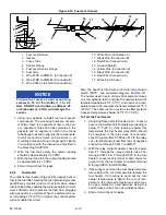
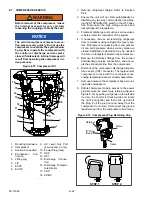
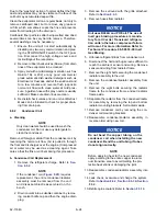
Figure 8.10 Fuel Level Sensor
1. Fuel Level Sensor
2. Gasket
3. Focus Tube
4. Sensor Flange
5. Fuel Level Sensor Flange
6. Fuel Tank
7. Wire FLSC to 2MM-13 (Connection C)
8. Wire FLSB to 2MM-24 (Connection B)
9. Wire PCM-22 to FLSA (Connection A)
10. White Wire (Connection C)
11. Black Wire (Connection B)
12. Red Wire (Connection A)
13. Ground (Shield)
14. Yellow Wire (Connection C)
15. Black Wire (Connection B)
16. Red Wire (Connection A)
17. Wires From Sensor
- - - - -
NOTICE
Torque fuel level sensor mounting
screws to 15 to 18 inch/lbs (1.7 to 2.0
Nm). DO NOT over tighten, as little as 20
inch/pounds (2.3 Nm) will damage the
sensor.
1. Using new gaskets, reinstall fuel level sensor
components. The mounting holes are not sym-
metrical, there is an alignment hole in the sen-
sor, alignment holes and index dimples in the
gaskets and an alignment notch in the focus
tube flange to assist in aligning the components.
Install mounting screws and washers in all
mounting holes and bring to finger tight. Tighten
in accordance with the instructions provided in
the preceding CAUTION.
2. With the fuel tank empty the output reading
should be approximately 0.25 VDC.
3. With the fuel tank full, the output reading should
be approximately 4.75 VDC.
4. Start unit and check for leaks.
8.5.8
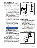
Fuel Heater
The optional fuel heater (
) applies heat to
fuel in the fuel filter. Heating the fuel dissolves/prevents
paraffin wax crystals (and ice) that form when diesel
fuel is chilled thus enabling the water separator to work
more efficiently and to prevent the filter from plugging
with wax and/or ice crystals. When the ambient air sen-
sor is reading 77°F (25°C) or higher, the control system
will not enable this circuit.
Also, the heater is fitted with an internal temperature
switch (FHTS - see schematic diagram,
).
The heater used in spin on type filter systems closes
on a temperature fall to energize the heater element at
temperatures below 45°F (7.2°C), and opens on a tem-
perature rise to de-energize the heater element at 75°F
(23.9°C). The heater used in suction side filter systems
closes at temperatures below 537°F (11.73.9°C).
To Test the Fuel Heater:
), check to
ensure the Ambient Air Temperature reading is
below 77°F (25°C), if the reading is below this
temperature the fuel heater relay (FHR) should
be energized. If the relay does not energize,
check for power from PCM fuse F10 to the relay
coil + terminal and ground from the coil negative
connection through PCM-17 to 3MM-17.
2. With the relay contacts closed, check for power
from F7, through the relay contacts, fuse F14,
through PCM-14 & 3 through SP25 to the fuel
heater connector at terminal A. Also check for
ground from the fuel heater connector terminal
B through SP10 to GND1RING1.
3. If the wiring is good and the fuel heater tempera-
ture is below the cut in temperature replace the
fuel heater. If the wiring is good but the fuel
heater temperature is above the cut out tem-
perature, the internal temperature switch may
be open. Retest at a temperature below the
switch close point as soon as conditions allow.
4. Start unit and check for leaks.
Summary of Contents for Vector 8500
Page 23: ...62 11640 1 6 1 3 SAFETY DECALS ...
Page 24: ...1 7 62 11640 62 03958 ...
Page 25: ...62 11640 1 8 ...
Page 26: ...1 9 62 11640 ...
Page 27: ...62 11640 1 10 ...
Page 125: ...62 11640 SECTION 6 MESSAGECENTER PARAGRAPH NUMBER Page 6 1 MESSAGECENTER MESSAGES 6 1 ...
Page 321: ......
Page 322: ......


