


7–15
62-11640
00023
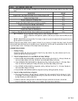
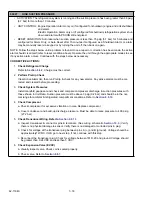
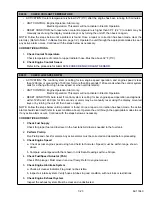
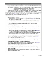
A/C CURRENT OVER LIMIT
• ACTIVATION: The high voltage amp draw is over the limit shown in the following table for more than 10 sec-
onds.
CONDITION
DRAW
Engine High / Low Speed, Standby Cool or Pretrip / Engine Off
30A
Engine High Speed Heat
18A
Engine Low Speed or Standby Heat
14A
Engine High Speed Defrost (With heaters energized)
16A
Engine Low Speed or Standby Heat Defrost
12A
Engine High/Low Speed or Null
8A
Engine Low Speed or Standby Null
8A
Engine or Standby Natural Defrost (when heaters are de-energized)
10A
• UNIT CONTROL: Engine Operation: Refrigeration system shutdown and alarm.
Electric Operation: Refrigeration system shutdown and alarm with PSCON still ener-
gized.
• RESET CONDITION: Auto reset after 15 minutes or alarm may be manually reset via keypad or by turn-
ing the unit OFF, then back ON.
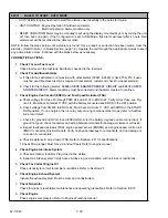
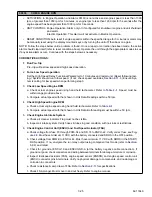
NOTE: Follow the steps below until a problem is found. Once a repair or correction has been made, the active
alarm should clear itself (see reset condition above). Operate the unit through the appropriate modes to see if
any active alarm occurs. Continue with the steps below as necessary.
CORRECTIVE ACTIONS:
1.
Perform
Pretrip
Clear Active Alarm list, then run Pretrip & check for any new alarms. Any active alarms must be cor-
rected and cleared before proceeding.
2.
Check Configurations for Correct Maximum Amps
Settings
a. Check DIESEL MAX GEN AMPS configuration setting. Setting should be 24 - 25 Amps. Maximum
recommended setting is 25 Amps. Minimum recommended setting is 22 Amps.
b. Check STANDBY MAX GEN AMPS configuration setting. Setting should be 22 - 25 Amps. Maxi-
mum recommended setting is 25 Amps. Minimum recommended setting is 22 Amps.
c. Check STARTUP MAX AMPS configuration setting. Setting should be 15 - 19 Amps. Maximum
recommended setting is 19 Amps.
d. Check DIESEL OFFSET MAX AMPS configuration setting. Setting should be 4 Amps.
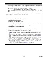
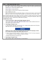
3.
Check For Electrical Failure
In System
a. Check electrical motors. Visually inspect condenser fans and evaporator fan for damage to motor
or fan blade, or for foreign material obstructing the movement of the fan. Listen for noise caused
by failed bearing or motor obstruction.
b. Check for defective wiring. Check for discolored wiring at contactors and loose connections.
c. Check for defective contactor. Remove and replace any suspected contactor(s).
Summary of Contents for Vector 8500
Page 23: ...62 11640 1 6 1 3 SAFETY DECALS ...
Page 24: ...1 7 62 11640 62 03958 ...
Page 25: ...62 11640 1 8 ...
Page 26: ...1 9 62 11640 ...
Page 27: ...62 11640 1 10 ...
Page 125: ...62 11640 SECTION 6 MESSAGECENTER PARAGRAPH NUMBER Page 6 1 MESSAGECENTER MESSAGES 6 1 ...
Page 321: ......
Page 322: ......


