


8–35
62-11640
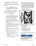
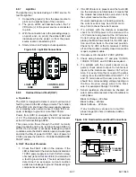
9. Slide the sub panel towards the front of the box
until the panel clears the lower studs, then tip
the sub panel out on the control box, see
(CCB2 is removed for clarity).
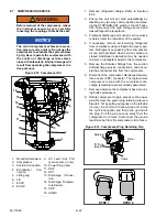
Figure 8.30 CCB Location in Control Box
10. Remove the four nuts and washers that secure
the CCB to the back of the panel. Carefully tip
the board up at an angle until the board is clear
of the mounting studs. Remove the board.
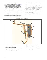
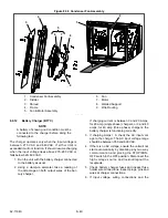
11. Install the new CCB, see
compete, the fastener stack should be in the fol-
lowing order (from top to bottom):
• Nylock nut
• Nylon washer
• CCB
• Nylon washer
• 4mm steel washer
• Standoff
Figure 8.31 CCB Location in Control Box
12. With the fastener stack in the correct order,
torque the 4 nylon nuts to 18 in/lbs.
13. Reinstall the sub panel, starting with the upper 2
bolts. Ensure that no wires are pinched in the
process.
14. Reverse disassembly procedure from this point
Torque all 6mm hardware to 4 ft/lbs (sub panel
nuts and bolts, PE plate nuts, current trans-
former nuts, and cover bolts).
15. Install negative battery cable.
16. Make sure the latest software has been loaded
to ensure all modules are compatible, refer to
.
NOTICE
When a module is replaced, software
should be upgraded before switching the
unit on. This will ensure software com-
patibility of all modules.
17. Turn SROS switch on and check for proper
operation of unit.
Change 09/14
Summary of Contents for Vector 8500
Page 23: ...62 11640 1 6 1 3 SAFETY DECALS ...
Page 24: ...1 7 62 11640 62 03958 ...
Page 25: ...62 11640 1 8 ...
Page 26: ...1 9 62 11640 ...
Page 27: ...62 11640 1 10 ...
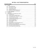
Page 125: ...62 11640 SECTION 6 MESSAGECENTER PARAGRAPH NUMBER Page 6 1 MESSAGECENTER MESSAGES 6 1 ...
Page 321: ......
Page 322: ......


