62-11640
7–16
00023
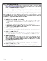
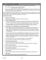
A/C CURRENT OVER LIMIT - CONTINUED
4.
Check High Voltage Components Amp
Draw (with the unit operating)
a. Check condenser fan amp draw on all legs. (CDCON)
b. Check evaporator fan motor amp WARNING draw on all 3 legs (1EVCON)
c. Check compressor amp draw on all 3 legs. (CCON)
d. Check heater amp draw. (1HTCON1, 1HTCON2, 2HTCON1, 2HTCON2, 3HTCON1 & 3HTCON2 - if
applicable)
WARNING
!
Caution and good electrical practices must be used when working around and with high
voltage circuits.
Verify that all three actual amperage readings for each component are within 10% of each other, and
are within the values shown in
5.
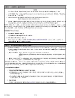
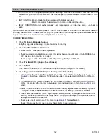
Check Generator Voltage (If Used When Alarm Occurred)
Check voltage at GENCON L1-L2, L1-L3, L2-L3. Must be within voltage limits shown in
6.
Check Power Source Voltage (If Used When Alarm
Occurred)
Check voltage at PSCON L1-L2, L1-L3, L2-L3. Must be within voltage limits shown in
7.
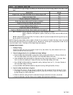
Check Voltage Output From
Contactors
a. Check voltage at GENCON T1-T2, T1-T3, T2-T3. Must be within voltage limits shown in
b. Check voltage at CCON with compressor operating. T1-T2, T1-T3, T2-T3. Must be within voltage
8.
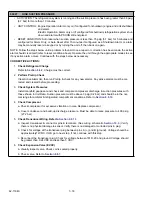
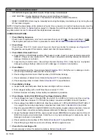
Verify Accuracy of AC Current
Sensor
a. Put microprocessor in PC Mode. Refer to
. Must have 0 AC1 Amps and 0 AC2 Amps
in Unit Data.
b. Use a clamp on ammeter to measure current draw of all 3 legs of the T side of GENCON. Meter
reading should be the same as Unit Data: Compare meter reading to Unit Data in PC Mode. Com-
pare meter reading to Unit Data with unit under load.
9.
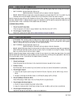
Defective Overload Ground Fault (OGF)
Detector
Opens prematurely. Remove and replace.
Summary of Contents for Vector 8500
Page 23: ...62 11640 1 6 1 3 SAFETY DECALS ...
Page 24: ...1 7 62 11640 62 03958 ...
Page 25: ...62 11640 1 8 ...
Page 26: ...1 9 62 11640 ...
Page 27: ...62 11640 1 10 ...
Page 125: ...62 11640 SECTION 6 MESSAGECENTER PARAGRAPH NUMBER Page 6 1 MESSAGECENTER MESSAGES 6 1 ...
Page 321: ......
Page 322: ......


