8–9
62-11640
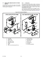
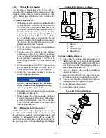
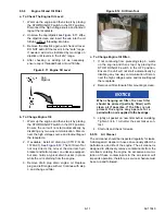
Figure 8.9 Suction Side Fuel Filter
8.5.6
Suction Side Fuel Filter Replacement
To Replace Filter:
1. Ensure the unit will not start automatically by
disabling any two way communication and plac-
ing the STOP/RUN-OFF switch in the OFF posi-
tion. Disconnect the high voltage source and
lockout/tagout the receptacle.
NOTE
If required, use a lock collar wrench (Carrier
Transicold part Number 07–00423–00) to
loosen the collar or vent cap. Do not use the
wrench to install the vent cap or collar, hand
tighten only.
2. Place a shallow pan under filter (
Remove the vent cap and open the drain valve
to drain the fuel below the collar level.
3. Remove the collar then remove the clear cover.
4. Remove filter element, spring, cover seal, and
vent cap seal. Dispose of the filter element and
seals properly.
5. Using a clean shop rag, clean the cover, collar
and threads on the filter body.
6. Install new filter element, cover seal and vent
cap seal. Install filter with spring at top and hand
tighten collar.
7. Prime the system by removing the vent cap from
the filter bowl and add fuel until level is about
even with the top of the filter element Reinstall
cap and hand tighten.
8. Start the engine and run for one minute. Slowly
open the vent cap and allow the fuel level to
drop to about one inch above the collar.
9. Hand tighten the vent cap.
8.5.7
Fuel Level Sensor (FLS)
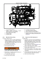
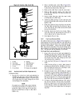
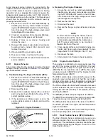
An optional fuel level sensor (
) supplies an
input signal to the control system as to the percent of
fuel remaining in the fuel tank. The control system will
activate alarm A00001 - “LOW FUEL LEVEL WARN-
ING” when the level reaches 15%, and (if configured to
do so) shuts the engine down when the level reaches
10%. The fuel tank level is displayed in Unit Data.
To Check The Fuel Level Sensor:
1. Ensure the unit will not start automatically by
disabling any two way communication and plac-
ing the STOP/RUN-OFF switch in the OFF posi-
tion. Disconnect the high voltage source and
lockout/tagout the receptacle.
2. Verify that the PCM fuse (F8,
open.
3. Verify that the wiring is correct, cable shield is
properly grounded and the condition of connec-
tors. No damage to sensor; no damage, mois-
ture or corrosion in connectors.
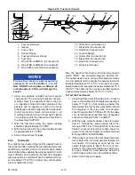
4. Energize sensor circuit, (MM calling for engine
operation). Check power (approximately 12
VDC) from PCM-22 (9,
) through to
connector (12). Check ground from 2MM-24 (8)
through connector (11). Check signal (greater
than 0.24 VDC and less than 5VDC) at 2MM-13.
5. If checks in the preceding step are OK, remove
the fuel level sensor, focus tube and gaskets.
With the trailer level, verify that the fuel level
sensor flange is within one-half bubble of level
using a 24 inch level. Adjust tank mounting as
required.
1. Collar
2. Vent Cap
3. Vent Cap Seal
4. Cover
5. Cover Seal
6. Spring
7. Filter Element
8. Check Valve
9. Drain Valve
10. Heater (if equipped)
Summary of Contents for Vector 8500
Page 23: ...62 11640 1 6 1 3 SAFETY DECALS ...
Page 24: ...1 7 62 11640 62 03958 ...
Page 25: ...62 11640 1 8 ...
Page 26: ...1 9 62 11640 ...
Page 27: ...62 11640 1 10 ...
Page 125: ...62 11640 SECTION 6 MESSAGECENTER PARAGRAPH NUMBER Page 6 1 MESSAGECENTER MESSAGES 6 1 ...
Page 321: ......
Page 322: ......


